
This is a followup of OT postings in thread Focal Clear Review (headphone) covering the consequences of insufficent filtering at the output of a DAC chip.
You can see this in practice at stereophile. @John Atkinson measures the behaviour of DACs using both broadband noise and a single 19.1 kHz sinus. A good example is the Holoaudio May, see figure 3:
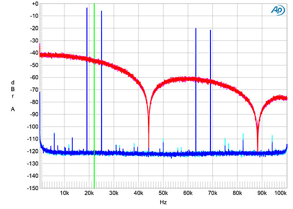
Fig.3 HoloAudio May, NOS mode, wideband spectrum of white noise at –4dBFS (left channel red, right magenta) and 19.1kHz tone at 0dBFS (left blue, right cyan) into 100k ohms with data sampled at 44.1kHz (20dB/vertical div.).
You can see that with the NOS filter the analog output signal in fact contains all mirror tones of 19.1 kHz.
The same DAC has a much better filter where the mirror signals are very well suppressed:
Nope. You do retrieve the 24.1 kHz if the reconstruction filter is poor or missing. See Ken. C. Pohlmann Principles of Digital Audio, in the 4th Edition from 2000 in chapter 4 Output Lowpass Filter on page 94. If you do not use a proper lowpass filter those mirror signal are contained in the analog signal.Maybe you’ve missed the theory.
Anyfbetween 0 and fs/2 at the output of a converter can be a mirror ofn x fs ± fat the input. “Converter” here means ADC or DAC.
So, in the case of a DAC @ 44.1kHz for example, 20kHz in analog can indeed be 24.1kHz in digital if that has not been properly filtered in the digital domain — but you don’t retrieve 24.1kHz in the analog domain.
You can see this in practice at stereophile. @John Atkinson measures the behaviour of DACs using both broadband noise and a single 19.1 kHz sinus. A good example is the Holoaudio May, see figure 3:
Fig.3 HoloAudio May, NOS mode, wideband spectrum of white noise at –4dBFS (left channel red, right magenta) and 19.1kHz tone at 0dBFS (left blue, right cyan) into 100k ohms with data sampled at 44.1kHz (20dB/vertical div.).
You can see that with the NOS filter the analog output signal in fact contains all mirror tones of 19.1 kHz.
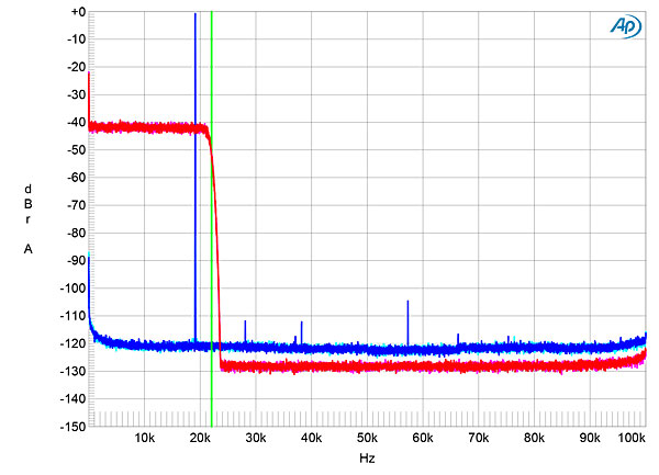
The same DAC has a much better filter where the mirror signals are very well suppressed:
Fig.5 HoloAudio May, OS mode, wideband spectrum of white noise at –4dBFS (left channel red, right magenta) and 19.1kHz tone at 0dBFS (left blue, right cyan) into 100k ohms with data sampled at 44.1kHz (20dB/vertical div.).
I don't understand this. If an analog 20 kHz signal is sampled the sampled sequence contains these signals:But that 20kHz in the analog domain could also be 64.1kHz (44.1 + 20), 68,2kHz (2x44.1 - 20), 108,2kHz, etc. etc. in the digital domain.
- 20 kHz (0*fs + 20) and 24.1 kHz (0*fs + fs/2 + (fs/2 - 20))
- 64.1 kHz (1*fs + 20) and 68.2 kHz (1*fs + fs/2 + (fs/2 - 20))
- 108.2 kHz (2*fs + 20) and 112.3 kHz (2*fs + fs/2 + (fs/2 - 20))
- ...
- N*fs + 20 and N*fs + fs/2 + (fs/2 - 20)
But I did retrieve it. If I find some time on the weekend I'll repeat this experiment with a second ADC (I cannot run the ADC and the DAC of the RME at different samplerates). The spectrum display in REW will show what's in the signal better than the time domain display of the DSO.Coming back to the RME DAC, not only did you only feed the DAC with a 20kHz pure wave (so no 24.1kHz was present at the input, thus no aliasing could theoretically happen), but also you cannot retrieve any 24.1kHz at the output (which means the analog oscilloscope graph cannot be that of 20kHz + 24.1kHz).
Since the input signal is not a single frequency but the sum of two (or more) you can't rely on what the DSO says.Your initial second screenshot btw shows f=17.57kHz, as opposed to the first showing f≃20kHz — not sure what that particularly means for your particular DSO.
 He actually never noticed that until performing a hearing test, and it didn’t prevent him to be very talented!