

-
Welcome to ASR. There are many reviews of audio hardware and expert members to help answer your questions. Click here to have your audio equipment measured for free!
You are using an out of date browser. It may not display this or other websites correctly.
You should upgrade or use an alternative browser.
You should upgrade or use an alternative browser.
Can anyone help with Alignment?
- Thread starter Robbie010
- Start date

- Thread Starter
- #203
Awesome. That is a good spot!I would try this tweak to try to deal with the issues above the intended range
New 12" Full-Range: Fane 12-250TC
the bigger brother of the Fane got a cone treatment / tweak https://www.diyaudio.com/community/threads/how-to-make-a-loudspeaker-sandwich-cone.402917/post-7467924www.diyaudio.com
Seems pretty cheap and easy to do.
Why are you using full range driver as a woofer btw?
I will defo try that.
As mentioned before, I wasn’t set on the midrange, I only knew I wanted horns and I wanted more flexibility when choosing crossovers so that I could control the size of the horn needed.
Also, as I said previously, this is the start of the project, not the end. I am open to changing drivers.

3ll3d00d
Addicted to Fun and Learning
- Joined
- Aug 31, 2019
- Messages
- 505
- Likes
- 367
cross at the right point for the drivers in use (and obviously use drivers that can meet each other nicely) and implement a competent crossover. If you do this then no problem, if you don't then problem. That's pretty much all there is to it.In any way, XO/EQ around 1 kHz would not be a good idea, it should be avoided as far as possible, as I wrote in my post #85.
- Thread Starter
- #205
Afternoon all.
I ran through the setup again this afternoon, I EQ'd each driver and applied the crossovers:

I now want to have another go at alignment but my question is, do I remove the crossover filters before hand?
I assume the crossover filters will throw-off the time alignment of 20hz-20khz sweep. Or, do I leave the crossover filters in place and only run short sweeps on each driver i.e. 100hz-1khz on woofer, 1khz-6khz on midrange and 5khz-20khz on tweeter??
My plan was to simply sweep each driver at the same distance with the mic central between the drivers and use the right tweeter as a time reference then eyeball the impulse response to roughly time align.
I ran through the setup again this afternoon, I EQ'd each driver and applied the crossovers:
I now want to have another go at alignment but my question is, do I remove the crossover filters before hand?
I assume the crossover filters will throw-off the time alignment of 20hz-20khz sweep. Or, do I leave the crossover filters in place and only run short sweeps on each driver i.e. 100hz-1khz on woofer, 1khz-6khz on midrange and 5khz-20khz on tweeter??
My plan was to simply sweep each driver at the same distance with the mic central between the drivers and use the right tweeter as a time reference then eyeball the impulse response to roughly time align.
Use these from @3ll3d00d With in room measurements you are not going to get meaningfully better.Afternoon all.
I ran through the setup again this afternoon, I EQ'd each driver and applied the crossovers:
View attachment 481668
I now want to have another go at alignment but my question is, do I remove the crossover filters before hand?
I assume the crossover filters will throw-off the time alignment of 20hz-20khz sweep. Or, do I leave the crossover filters in place and only run short sweeps on each driver i.e. 100hz-1khz on woofer, 1khz-6khz on midrange and 5khz-20khz on tweeter??
My plan was to simply sweep each driver at the same distance with the mic central between the drivers and use the right tweeter as a time reference then eyeball the impulse response to roughly time align.
T = 0.797
M = 0.5839
vs the W
i.e. they are later
- Thread Starter
- #207
Thanks.
I seem to be two steps forward and 3 steps back at the minute..... a couple of questions........ then I'll leave you alone....... for the rest of today....
When viewing an overlayed impulse response, like the one below, all measurements taken with an acoustic time reference and the reference being at 0ms, am I wrong in assuming that the tweeter is the earliest response i.e closest to 0ms, then the midrange and then the woofer. So, both the midrange and tweeter should be delayed to align with the woofer?

Secondly, this afternoon I took 2 sweeps of the tweeter and applied a 10ms delay between them, however, when I view the sweeps in the impulse overlay they perfectly align. I was expecting there to be an obvious 10ms gap between the impulses, why is this not the case?

I seem to be two steps forward and 3 steps back at the minute..... a couple of questions........ then I'll leave you alone....... for the rest of today....
When viewing an overlayed impulse response, like the one below, all measurements taken with an acoustic time reference and the reference being at 0ms, am I wrong in assuming that the tweeter is the earliest response i.e closest to 0ms, then the midrange and then the woofer. So, both the midrange and tweeter should be delayed to align with the woofer?
Secondly, this afternoon I took 2 sweeps of the tweeter and applied a 10ms delay between them, however, when I view the sweeps in the impulse overlay they perfectly align. I was expecting there to be an obvious 10ms gap between the impulses, why is this not the case?
The first graph looks reasonable and yes tweeter is first followed by mid followed by woofer. You can go down the rabbit hole of "what" exactly to align i.e. first zero crossing, front, peak, etc. (with filters and room effects it can be hard to tell exactly what you are looking at) or you can use the delays given to your previously which will certainly work.Thanks.
I seem to be two steps forward and 3 steps back at the minute..... a couple of questions........ then I'll leave you alone....... for the rest of today....
When viewing an overlayed impulse response, like the one below, all measurements taken with an acoustic time reference and the reference being at 0ms, am I wrong in assuming that the tweeter is the earliest response i.e closest to 0ms, then the midrange and then the woofer. So, both the midrange and tweeter should be delayed to align with the woofer?
View attachment 481684
Secondly, this afternoon I took 2 sweeps of the tweeter and applied a 10ms delay between them, however, when I view the sweeps in the impulse overlay they perfectly align. I was expecting there to be an obvious 10ms gap between the impulses, why is this not the case?
View attachment 481687
RE: second graph. When I do these types of measurements I don't take 2 measurements rather I set the delay between two drivers and measure them with one sweep and then you should be able to see both impulses and you can subtract the delay you set and the remainder is the offset. This was discussed somewhere else but I think REW looks a the waveform to set the timing reference so if you take 2 sweeps even though you set a delay REW goes by the wave form, so they will drop right on top of each other just like you found. Here is a link from MiniDSP that explains the process for their device but it should point you in the right direction https://www.minidsp.com/applications/rew/measuring-time-delay.
Now, this is your time to compare the REW-method/results for time alignment with another independent methods/results.
While using/applying your present optimized XO configurations, you may try the following three method (ref. #53), only if you would be interested;
Primitive but reliable reproducible "Time-shifted multiple-Fq-tone-bust method";
- Precision measurement and adjustment of time alignment for speaker (SP) units: Part-1_ Precision pulse wave matching method: #493
"Multiple-Fq-simultaneous-tone-burst energy-peak matching method";
- Precision measurement and adjustment of time alignment for speaker (SP) units: Part-2_ Energy peak matching method: #494
"Single sine-wave matching method";
- Precision measurement and adjustment of time alignment for speaker (SP) units: Part-3_ Precision single sine wave matching method in 0.1 msec accuracy: #504, #507
I will soon send/share the test tone signals I prepared/applied in these three methods through PM communication with you.
If you would be interested in sharing your comparative results here on this thread, I (we?) will be happy to see them!
- Thread Starter
- #210
After applying the new crossover settings and the delays that @3ll3d00d supplied, I took your advice and did some subjective listening (with a beer or two) and I must say, I'm already most impressed.
Just as I wanted, a lovely clean presentation, tight bass, slightly forward, which I'm sure is down to the mid horns and plenty of detail with well recorded tracks. At this stage, it's not the deepest soundstage and I still need to deal with the gain hiss but I'll get there.
However, if this is what can be achieved already by anumpty novice, like myself - obviously with a little help from you guys - I'm very happy.
Thanks everyone.
More to follow.
Just as I wanted, a lovely clean presentation, tight bass, slightly forward, which I'm sure is down to the mid horns and plenty of detail with well recorded tracks. At this stage, it's not the deepest soundstage and I still need to deal with the gain hiss but I'll get there.
However, if this is what can be achieved already by a
Thanks everyone.
More to follow.
- Thread Starter
- #211
Good morning all!
I'm wondering if anyone can tell me whats going on here……
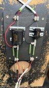
Following some advice, I decided to knock up a small board with protection capacitors and Lpads to try and tame the hiss I hear. I was advised to use a 68uf cap for the midrange and 10uf cap for the tweeter. Using an online calculator I went with 2.2ohm 10w Rseries and 22ohm 10w Rparallel, which worked out at 8.5ohm and 2.8db attenuation:


When I hooked this up to one speaker the hiss was completely gone from the midrange and tweeter..... hurrah I hear you shout!
However, along with the hiss went all the sound, in order to get the merest of audio to play I had to turn the input gain from 0db to +12db and output gain from -34db to +12db for the slightest sound.
Help!
I'm wondering if anyone can tell me whats going on here……
Following some advice, I decided to knock up a small board with protection capacitors and Lpads to try and tame the hiss I hear. I was advised to use a 68uf cap for the midrange and 10uf cap for the tweeter. Using an online calculator I went with 2.2ohm 10w Rseries and 22ohm 10w Rparallel, which worked out at 8.5ohm and 2.8db attenuation:
When I hooked this up to one speaker the hiss was completely gone from the midrange and tweeter..... hurrah I hear you shout!
However, along with the hiss went all the sound, in order to get the merest of audio to play I had to turn the input gain from 0db to +12db and output gain from -34db to +12db for the slightest sound.
Help!
Attachments
Are you simulating a variable passive attenuators with Lpads?
If so, my post here would be of your reference...
Prior to complete elimination of my passive attenuators for my 8 Ohm midrange, tweeter and super-tweeter, I very much carefully observed and measured the R1, R2 and R1+R2 resistance values of the excellent attenuators (ref. here #248 on my project thread).
You would please carefully look and study these three diagrams which were before implementation of the protection capacitors.
- Thread Starter
- #214
Good evening all.
I’ve made a little more progress over the last week or so tweaking the main speakers and I’m slowly getting there.
I have now built a subwoofer and will be trying to integrate it this week, so I’m wondering what the process should be?
Initially, I was thinking I should treat the subwoofer like another driver, measure it near-field, flatten its response and dial in a crossover then adjust the time alignment and gain with the subwoofer in-place while measuring at the seating position?
3ll3d00d
Addicted to Fun and Learning
- Joined
- Aug 31, 2019
- Messages
- 505
- Likes
- 367
What did you build? A sealed DIY sub will generally need some sort of correction to bring up the low end. a pro driver often has a rising response so may need something like a negative high shelf to flatten it while a ported sub commonly needs a protective high pass filter to prevent it unloading below tune.
These are all design Q's though not so much in room issues.
These are all design Q's though not so much in room issues.
Last edited:
- Thread Starter
- #216
What did you build? A sealed DIY sub will generally need some sort of correction to bring up the low end. a pro driver often has a rising response so may need something like a negative high shelf to flatten it while a ported sub commonly needs a protective high pass filter to prevent it unloading below tune.
These are all design Q's though not so much in room issues.
I used a GRS 12W-4HE driver and built a sealed cabinet, which works out at roughly 42L after subtracting the driver and bracing.
3ll3d00d
Addicted to Fun and Learning
- Joined
- Aug 31, 2019
- Messages
- 505
- Likes
- 367
It's rolling off from ~70Hz so what's the goal? ie output level, extensionI used a GRS 12W-4HE driver and built a sealed cabinet, which works out at roughly 42L after subtracting the driver and bracing.
Typically you will add some sort of LT or low shelf here but this needs to modelled along with excursion and power then checked against those design goals.
- Thread Starter
- #218
It's rolling off from ~70Hz so what's the goal? ie output level, extension
Typically you will add some sort of LT or low shelf here but this needs to modelled along with excursion and power then checked against those design goals.
I was posting about the sub build in DIY Audio and someone kindly modelled the sub for me:
I just built a sealed sub and agree with @3ll3d00d. Take a nearfield measurement (or much better go outside for a ground plane measurement, In room subwoofer measurements at the LP are useless for speaker design) and bring it into REW and add a low shelf filter, experimenting with different slopes and frequencies, until you get a filter with reasonably flat response. Leave some roll off below 40 Hz as you will get some room gain. That should get you a reasonable starting point for further integration.I used a GRS 12W-4HE driver and built a sealed cabinet, which works out at roughly 42L after subtracting the driver and bracing.
After that you need to integrate your sub and you will get a lot of conflicting advice and the science is far from settled. My free internet advice is keep the sub close to and centered between the mains. If you can get the sub close and centered try a linear phase crossover, if not then use minimum phase crossovers. Getting the timing right with in-room measurements is always hard. I usually end up using nearfield timing from REW and then a tape measure. A sealed DIY sub without a lot of DSP (beyond the shelf filter) will be relatively easy to integrate compared to many commercial subs which go crazy with DSP to push FR lower than optimal to meet marketing specs. Good luck.
I essentially agree with you. The advanced software tools, including REW, not always give you true and precise measurement results and tuning directions/suggestions, especially in time-alignment between sub-woofer(s) and main SPs at your listening position, as you @levimax wrote in your post #167 that "REW alignment tool does not work for LF / Woofers or sub woofers (works fine for Mid to Tweeter)."Getting the timing right with in-room measurements is always hard.
This is why I suggested OP @Robbie010 to try the primitive but reliable fully-validated reproducible "Time-shifted multiple-Fq-tone-bust method" as shared in my post #53 together with other two methods.
1. Primitive but reliable reproducible "Time-shifted multiple-Fq-tone-bust method";
- Precision measurement and adjustment of time alignment for speaker (SP) units: Part-1_ Precision pulse wave matching method: #493
2. "Multiple-Fq-simultaneous-tone-burst energy-peak matching method";
- Precision measurement and adjustment of time alignment for speaker (SP) units: Part-2_ Energy peak matching method: #494
3. "Single sine-wave matching method";
- Precision measurement and adjustment of time alignment for speaker (SP) units: Part-3_ Precision single sine wave matching method in 0.1 msec accuracy: #504, #507
In case if you would be seriously interested in applying these methods in your setup, I would be more than happy sharing the test-tone signals I prepared and applied; please simply PM contact me writing your wish.
Last edited:
Similar threads
- Replies
- 14
- Views
- 794
- Replies
- 3
- Views
- 349
- Replies
- 68
- Views
- 7K

- Replies
- 36
- Views
- 2K