• WANTED: Happy members who like to discuss audio and other topics related to our interest. Desire to learn and share knowledge of science required. There are many reviews of audio hardware and expert members to help answer your questions. Click here to have your audio equipment measured for free!

Buying my 1st pro audio interconnect cable and soldering myself

Speedskater

Major Contributor
Joined
Mar 5, 2016
Messages
1,634
Likes
1,357
Location
Cleveland, Ohio USA
You don’t need the strand count if you have the impedance, capacitance and inductance. This is all you need to know for ”any” cable.
Cables are used for lots of different purposes. Each purpose has it's own list of requirements.
a] RCA analog interconnect: Shielding and low end-to-end resistance of the shield.
b] RCA digital interconnect: Radio Frequency Characteristic Impedance.
c] XLR analog interconnect: Shielding and symmetry of the central conductors.
d] XLR mic cable: above [c] and robust construction, flexibility and low handling noise.
e] XLR digital interconnect: Shielding and Radio Frequency Characteristic Impedance.
f] speaker cable: low end-to-end resistance.
g] AC power cable: low end-to-end resistance and 'UL' listing.
 

joeren

Member
Joined
Nov 27, 2020
Messages
34
Likes
73
Cables are used for lots of different purposes. Each purpose has it's own list of requirements.
a] RCA analog interconnect: Shielding and low end-to-end resistance of the shield.
b] RCA digital interconnect: Radio Frequency Characteristic Impedance.
c] XLR analog interconnect: Shielding and symmetry of the central conductors.
d] XLR mic cable: above [c] and robust construction, flexibility and low handling noise.
e] XLR digital interconnect: Shielding and Radio Frequency Characteristic Impedance.
f] speaker cable: low end-to-end resistance.
g] AC power cable: low end-to-end resistance and 'UL' listing.
I completely understand the use of cables and their differences. I’m a retired High Frequency Power Electronics Technician. For audio frequency use, the dominant parameters are those terms that I mentioned. Unless defective, there is no audible difference in meter length cables,
 

Speedskater

Major Contributor
Joined
Mar 5, 2016
Messages
1,634
Likes
1,357
Location
Cleveland, Ohio USA
For audio frequency use, the dominant parameters are those terms that I mentioned. Unless defective, there is no audible difference in meter length cables,
Those statements are incorrect.
For reasonable cable lengths & designs impedance (75 Ohm RFCI), capacitance and inductance only apply to digital cables.
 
Last edited:

joeren

Member
Joined
Nov 27, 2020
Messages
34
Likes
73
Those statements are incorrect.
For reasonable cable lengths & designs impedance (75 Ohm RFCI), capacitance and inductance only apply to digital cables.What
That’s not a good argument. We’re not talking about transmission lines or characteristic impedance. We’re talking audio frequencies.
 

AnalogSteph

Major Contributor
Joined
Nov 6, 2018
Messages
3,373
Likes
3,317
Location
.de
My setup consist of:

1. Two 4 meters local brand 2 core 20/0.012 + 1 shielded 94/0.12 ( AWG 24 TC material ), 1/4 inch TRS balanced cable from subwoofer output to eris 3.5.
2. One 3 meters Right angle 3.5mm to dual RCA canare L-2t2s.
That looks problematic.

Let's recap the equipment.
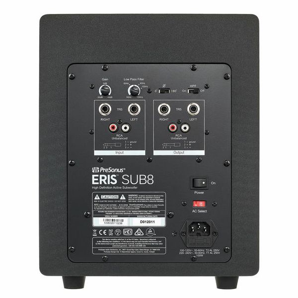
The Eris Sub8 is this guy:
16226371_800.jpg

IEC Class I, balanced TRS + unbalanced RCA in and out.

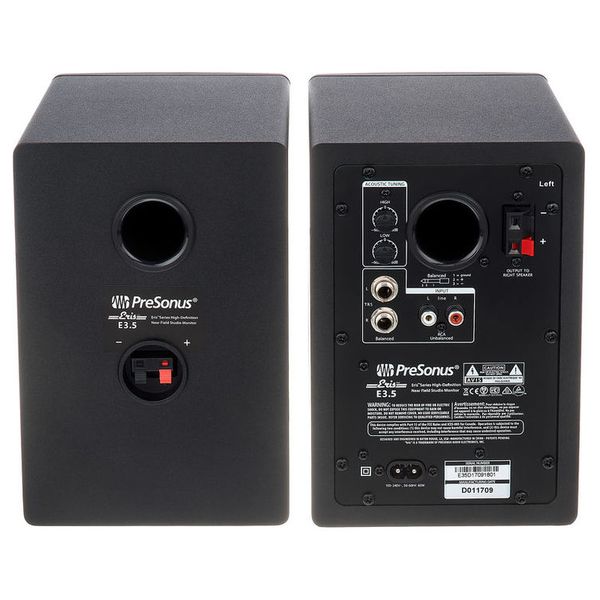
And these are the Eris E3.5:
12790352_800.jpg

IEC Class II, balanced TRS + unbalanced RCA in and out.

You could go balanced into the sub and continue unbalanced into the monitors, but vice versa is likely to be problematic since I assume you are just plugging the 3.5 mm into a regular old PC, another IEC Class I device. That's ground loop issues almost guaranteed. Before waxing lyrical about cables, I would definitely advise sorting that problem out first.

If my previous assumptions are correct, this is the kind of cable you want to be making for the PC --> sub connection:
3.5 mm side: Connect shield L, shield R, cold L, cold R to sleeve (ground). Hot L to tip, hot R to ring.
2x 1/4" TRS side: Leave shields unconnected here. Cold L/R goes to respective ring, Hot L/R to respective tip.

Besides, I would recommend ditching the E3.5s as soon as you can. These are decent enough multimedia speakers, but their on-axis response is poor, and since I have set up a pair in the past, I can confirm that vertical dispersion is very uneven (due to the ultra-simple passive crossover, I'm guessing the usual single capacitor).
Erin's review

At the very least, a good helping of EQ is recommended to flatten out the response to an acceptable degree. Erin lists some DSP suggestions that I would look into. (You can reproduce the settings given e.g. in PEACE. Note: Equalizer APO only works for shared mode playback, so if you insist on exclusive mode output, PEQ would have to be done within the player.)
 

Audiofire

Addicted to Fun and Learning
Forum Donor
Joined
Feb 8, 2022
Messages
632
Likes
354
Location
Denmark
5. I think the easiest way to determine if an interconnect cable is well design or not (aka snake oil) is through a studio monitor, less varieble means easier to catch the differences. For me it definitely reveal the material, design, shielding, frequency responseand transcient ofIC cable well enough.
6. From engineer perspective, I think IC cable do drastically affect the sound and need good design and manufacturing. It's not all snake oil like those non-engineer claimed, except maybe the price. But then again,so do all the 5 figures hifi system...
Hearing is actually one of the worst ways to decide whether an analog interconnect is well designed, because of psychoacoustics that also lead you to hear a difference that was not there.

Your conjecture would have at least a little significance if you upload a video to YouTube that shows a proper blind test, where you try to guess which of a known selection of cables was connected by someone else (so that you don't know which cable was connected). This will show you whether there is a real difference in how cables sound.

Pro tip: There is no difference in how audio cables sound, unless there is a worrying amount of ignorance involved.

Wow.

Your image manipulation skills are at a whole other level aren't they? :facepalm:
The image is meant as a joke. The man in the image is Paul McGowan, a meme by now due to how he uses hearing instead of measurements to decide his "audiophile" preferences. When they are in reality audiophoolery preferences, so the image is a very accurate description of the original poster in the thread.

But I disagree to your statement they will all sounded the same. Different materials, gauge, strands count, strands size, oxidization level, even current load ,temperature, dielectric, shielding method, length and etc will had different effect to the signal that will be boosted tenth to hundreds times.
The correct way to test an analog interconnect is by using an audio interface, where input and ouput channels are connected directly with the cable. This is loopback testing used by professional engineers. You still have a long way to go in your engineering knowledge if you disagree with this method.

Here is an example of how to do this properly, and shows that even the cheapest RCA cable has no effect on the sound when used with well designed equipment...

You can make an internal loopback recording without the cable by playing a FLAC file and recording with Audacity for example. Compare the audio file recorded through the cable with the original audio file and internal loopback, for example by overlaying the waveforms and spectrograms or by measuring distortion with Room EQ Wizard (REW). However loopback testing requires a well designed audio interface, but that should be a top priority if you are an audiophile anyway:

For reasonable cable lengths & designs impedance (75 Ohm RFCI), capacitance and inductance only apply to digital cables.
And turntable cartridges. :)
 
Last edited:
Top Bottom