• WANTED: Happy members who like to discuss audio and other topics related to our interest. Desire to learn and share knowledge of science required. There are many reviews of audio hardware and expert members to help answer your questions. Click here to have your audio equipment measured for free!

Building A Reactive Load for Amplifier Testing

OP
amirm

amirm

Founder/Admin
Staff Member
CFO (Chief Fun Officer)
Joined
Feb 13, 2016
Messages
44,657
Likes
240,864
Location
Seattle Area
Well if you are going to limit frequencies I think you still need more than one. Maybe 50 hz, 1 khz and 10 khz. Among other things I think you'll find reactive loads will alter the FR of amps. I think this contributes to a different sound even if the amp isn't fully over-driven or overwhelmed.
I can vary the frequency at ease it is just that none of the reactance will be the stated ones anymore. As John mentioned, maintaining those settings would hugely multiply complexity.
 

March Audio

Master Contributor
Audio Company
Joined
Mar 1, 2016
Messages
6,378
Likes
9,321
Location
Albany Western Australia
Well if you are going to limit frequencies I think you still need more than one. Maybe 50 hz, 1 khz and 10 khz. Among other things I think you'll find reactive loads will alter the FR of amps. I think this contributes to a different sound even if the amp isn't fully over-driven or overwhelmed.
As others said it could get crazy complex, you will need separate L and C loads for the different frequencies
Inductive reactance is 2*PI*F*L
Capacitive Reactance is 1/ 2*PI*F*C

However I do see validity in testing a a low and a high frequency, 1KHz and 10kHz. It should be borne in mind that in real world HF content drops off quite quickly so will never be taxing the amp like the LF range.
 

Blumlein 88

Grand Contributor
Forum Donor
Joined
Feb 23, 2016
Messages
20,759
Likes
37,600
Okay, maybe we need to back up and ask why do this.

Why does performance with a reactive load matter? Because you could have two amps with identical specs on 8 ohm resistors that react differently with 8 ohm reactive loads. Let us say a pair of 40 watt amplifiers.

Why does this happen or what happens?

Firstly a reactive load has an impedance that varies with frequency, so if an amplifier has more output impedance vs another, it will have a more variable frequency response. This is so simple you don't really need to test it. You can measure output impedance and match it with the impedance curve of your speaker to see if it matters.

Another difference could be limited current. It would need 2.25 amps at 8 ohms to manage 40 watts into a resistor. Let us say its max current is only 2.5 amps. If the load were an 8 ohm impedance with a 45 degree phase angle it would require 3.17 amps. If one 40 watt amp has 2.5 amp current max and the other has 20 amps current max one will run out of steam and distort while the other will not care.

Yet another difference is thermal dissipation capability of the output stage. 40 watts into 8 ohms in a resistor is one thing. If it is 8 ohms impedance with a 45 degree phase angle the output stage will see 17.1 watts come back from the load and have to dissipate that extra heat. If one amp is a proper amp with good external heatsinks and appropriately sized output components then no problem. If it has a flimsy excuse for heatsinks internally like a cheap AVR those extra watts being dissipated could in time overheat the output stage.

I think these are the main things making a reactive load difficult for an amp.

The first is a simple measurement of output impedance to know what we want to know.

Current capability can be determined by simply using a lower impedance. So maybe test at 1, 2, 4, 8 and 16 ohms with 500 hz or 1 khz. You really don't need reactance to determine that. Just need to know the current capability.

The thermal dissipation issue is a tougher one. Do some of you know a good non-destructive way to test this? Just off the top of my head one issue is class D, class A, class AB amps are different animals in this regard.

Can tone burst testing into different impedances tell us just as much with less danger?

If I've missed something important don't be shy about saying so. It is late where I am, was a long day, and maybe I'm just dense right now.

Random other things:

Not very common, but you can run into voltage limiting at higher impedances.

You could have instability caused by reactive loads and unstable feedback arrangements, but you'll likely only see this at high and low frequencies most of the time, and hopefully they are a thing of the past.

Some amps have advanced protection circuitry to protect themselves these days, and that interferes with obtaining limits of operation in testing.
 

maxxevv

Major Contributor
Joined
Apr 12, 2018
Messages
1,872
Likes
1,964
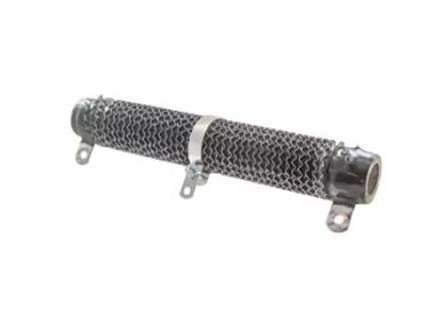
A simple way to vary the resistance / impedance is really just an adjustable wire wound resistor that can take a lot of power.

A pair of these in parallel will be just nice for up to 600W of load and 8 Ohms at max.

https://sg.rs-online.com/web/p/adjustable-resistors/8930902/

R8930902-01.jpg

Not sure how you can vary the reactance as that's a level of electronics beyond me. Maybe a serial board of capacitors in parallel and connector similarly connected in parallel with adjustable contact points to select total capacitance ?
 

RayDunzl

Grand Contributor
Central Scrutinizer
Joined
Mar 9, 2016
Messages
13,250
Likes
17,187
Location
Riverview FL
Not very common, but you can run into voltage limiting at higher impedances.

Why would an "easy" load limit voltage?

Maybe I just don't understand what you're referring to.
 

Blumlein 88

Grand Contributor
Forum Donor
Joined
Feb 23, 2016
Messages
20,759
Likes
37,600
Why would an "easy" load limit voltage?

Maybe I just don't understand what you're referring to.

It doesn't limit voltage, but you need higher voltage to get more watts out of it. So like when you need current, but it is limited, you can need voltage, but it is limited.

In my example. Say your 40 watt amp has 18 volts to put thru 8 ohms. Into 16 ohms it will only do 20 watts. In the case of the Quad and Soundlab there are frequencies with more than 20 ohms impedance. In the Quad it is right in the power range, between 50 hz and 100 hz. So a high powered rather low current amp would have more voltage, and could get you more bass power out of the Quad. Because it has more voltage available. A lower voltage high current amp might not do very well for the Quad.
 

KSTR

Major Contributor
Joined
Sep 6, 2018
Messages
2,764
Likes
6,187
Location
Berlin, Germany
A rule of thumb for amp designers is that the momentary current of a speaker / speaker driver with transient (non-sinusodial) waveforms can reach three times the DC value or even more, and therefore it is a good idea to assume a factor of ~4 for peak current capability margins. That is, a speaker with 3.3Ohms DCR may draw the same amount of peak current than a 1Ohm resistor. See, for example, "Designing Audio Power Amplifiers" by Bob Cordell.
The most problematic speakers are often large two-ways with low Qts / high Qms woofers because the woofer is operating on a large bandwidth which makes it easier for the critical waveforms to actually reach it. A real-world critical music test signal I found for this is the track "Dear Mr. Man" from the Prince album "Musicology" which sports a hard-clipped snare that triggers those high transient currents.

For a simple test of this, not tackling the output stage SOA protection for reactive loads but checking output stage and PSU instantanous current limiting, therefore use a sine burst test with resistive load of 1/4th the value the amp is spec'd for. That's why there is a need for 1Ohm non-reactive load to test 4Ohms rated amps with sine signals.
 
Last edited:

KSTR

Major Contributor
Joined
Sep 6, 2018
Messages
2,764
Likes
6,187
Location
Berlin, Germany
Another difference could be limited current. It would need 2.25 amps at 8 ohms to manage 40 watts into a resistor. Let us say its max current is only 2.5 amps. If the load were an 8 ohm impedance with a 45 degree phase angle it would require 3.17 amps.
Ehhm, that is not correct. Any impedance of a certain magnitude (say, 8Ohms) always draws the same current (by definition, literally), just at a different phase angle. The phase angle causes less dissipation in the load and higher dissipation in the output stage (but PSU power remains the same).
What you meant is probably this: When we parallel a pure reactance to an 8Ohms resistance to yield a +-45deg phase angle the impedance has fallen to 8/sqrt(2)=5.6 Ohms and that draws more current, accordingly.
 
OP
amirm

amirm

Founder/Admin
Staff Member
CFO (Chief Fun Officer)
Joined
Feb 13, 2016
Messages
44,657
Likes
240,864
Location
Seattle Area
What you meant is probably this: When we parallel a pure reactance to an 8Ohms resistance to yield a +-45deg phase angle the impedance has fallen to 8/sqrt(2)=5.6 Ohms and that draws more current, accordingly.
If we are to mimic PowerCube, then the impedance will always be the same. As such we won't be operating in the above mode.
 

restorer-john

Grand Contributor
Joined
Mar 1, 2018
Messages
12,705
Likes
38,856
Location
Gold Coast, Queensland, Australia
I'd like to see us standardize on the components when all is said and done. If we are going be winding custom inductors (likely), the same standards need to apply. That will enable consistent and comparable test environments and results that can be shared and crosschecked.

Options could be the method of switching the various load combinations and the type of control or interface if required for automated or semi-automated acquisition.

I really think this would be a worthwhile group design project and could inject some collaborative fun here. (not that it isn't fun already)
 
OP
amirm

amirm

Founder/Admin
Staff Member
CFO (Chief Fun Officer)
Joined
Feb 13, 2016
Messages
44,657
Likes
240,864
Location
Seattle Area
Audio Precision has a set of simple GPIO pins. We could use them as individual bits to select or binary code them and use a decoder inside the box. It is easy then to use an automated script to generate all the data in one shot. If we use a micro, we can use a simple up/down button on the unit to select the load as well.
 

KSTR

Major Contributor
Joined
Sep 6, 2018
Messages
2,764
Likes
6,187
Location
Berlin, Germany
For smaller output powers it might be easier to design an active load with another (rather beefy) amp which should be fully floating on both signal and PSU sides (to allow easy testing of balanced/bridged outputs, though there are ways to handle this with other tricks that don't need full isolation). This load amp is connected to the DUT with a low-value plain resistor (~1Ohms). By injecting the proper correlated signal to that amp any four-quadrant load condition can be established. In many cases the other channel of a stereo DUT amp can be used for this but then the test signals and the base load resistor(s) must be choosen with greater care. Simple (somewhat silly) example to explain this need: To test 4Ohms resistive load one would basically choose a 4 Ohm resistor which is virtually connected to GND by keeping the second channel at 0V. But this would stress the output stage dissipation of the second channel way more than the channel to be tested.
 

restorer-john

Grand Contributor
Joined
Mar 1, 2018
Messages
12,705
Likes
38,856
Location
Gold Coast, Queensland, Australia
For smaller output powers it might be easier to design an active load with another (rather beefy) amp which should be fully floating on both signal and PSU sides (to allow easy testing of balanced/bridged outputs, though there are ways to handle this with other tricks that don't need full isolation).

I considered this too. The issue is standardization, ease of access to the same 'rather beefy' amplifier and ensuring it is in spec all the time.

Passive networks appear on the face of it, to be a better option.
 

Speedskater

Major Contributor
Joined
Mar 5, 2016
Messages
1,643
Likes
1,364
Location
Cleveland, Ohio USA
I think that you need one load for reasonable/conventional loudspeakers and another load for special cases like Apogee and electrostatic speakers. A person would be silly to spend extra money on an amp designed for the special cases tat they don't own.
 

Willem

Major Contributor
Joined
Jan 8, 2019
Messages
3,722
Likes
5,353
I am certainly interested in the results of this execise. As a lifetime Quad electrostatic owner I have always cautiously stuck to Quad´s own amplifiers (a 303 with the ELS 57 and now a 606-2 with the 2805), and, to be honest, not regretted it. So I would love to see how their large current dumpers like my 606-2 or the modern Artera are testing. And I would love to know if, in fact, I have a lot more options, or not.
 

FrantzM

Major Contributor
Forum Donor
Joined
Mar 12, 2016
Messages
4,376
Likes
7,873
At the risk of looking dense and be labelled a fan boy:

I love ASR!!

More seriously though. This seems to be making the case that amps may indeed sound different ... on some speakers at least.

Just saying,,,
 

Willem

Major Contributor
Joined
Jan 8, 2019
Messages
3,722
Likes
5,353
Good amplifiers have a flat response under different loads, bad ones (including many tubes) don't.
 

Blumlein 88

Grand Contributor
Forum Donor
Joined
Feb 23, 2016
Messages
20,759
Likes
37,600
Ehhm, that is not correct. Any impedance of a certain magnitude (say, 8Ohms) always draws the same current (by definition, literally), just at a different phase angle. The phase angle causes less dissipation in the load and higher dissipation in the output stage (but PSU power remains the same).
What you meant is probably this: When we parallel a pure reactance to an 8Ohms resistance to yield a +-45deg phase angle the impedance has fallen to 8/sqrt(2)=5.6 Ohms and that draws more current, accordingly.
Yes, it was late and I was tired. A stupid mistake. Thank you for the correction.

Just as you surmised I had in mind a paralleled pair of 16 ohm devices or a series pair of 4 ohm devices that don't add up to 8 ohms. Which isn't 8 ohms impedance at 45 degrees phase angle, but 5.66 ohms at 45 degree phase angle.
 
Last edited:

Blumlein 88

Grand Contributor
Forum Donor
Joined
Feb 23, 2016
Messages
20,759
Likes
37,600
At the risk of looking dense and be labelled a fan boy:

I love ASR!!

More seriously though. This seems to be making the case that amps may indeed sound different ... on some speakers at least.

Just saying,,,
Yes, I've said before I think amplifiers with certain speakers still have a sound.
So am I correct or incorrect as long as the speakers or amps aren't pathological?

Is the reactive load testing going to tell us anything about that?
 

sergeauckland

Major Contributor
Forum Donor
Joined
Mar 16, 2016
Messages
3,460
Likes
9,158
Location
Suffolk UK
Years ago, when magazines still employed engineers to do reviews, HiFi News used an 8ohm load in parallel with 2uF as their standard test load. They did all THD and square wave testing into that load and compared it to the non-reactive pure 8ohm load. It fail to see why that can't be the ASR standard as it will suitably stress amplifiers, especially when combined with 4 and 2ohm resistive loads, go down to 1ohm if you must. If an amp can have low THD into the resistive loads and generate decent square waves into the reactive load, there's not a lot wrong with it.

S
 
Top Bottom