Really it seems a waste of time to keep measuring gear from certain companies once they have shown that they make stuff that doesn't do anything. Meanwhile there is a big queue of stuff much more worthwhile to look at.

-
WANTED: Happy members who like to discuss audio and other topics related to our interest. Desire to learn and share knowledge of science required. There are many reviews of audio hardware and expert members to help answer your questions. Click here to have your audio equipment measured for free!
You are using an out of date browser. It may not display this or other websites correctly.
You should upgrade or use an alternative browser.
You should upgrade or use an alternative browser.
AudioQuest Victoria Audio Cable with DBS Review
- Thread starter amirm
- Start date
OP
- Thread Starter
- #122
I know that. You said there is DC bias. You don't get DC bias like that. The inner wire is not connected to the signal wires so no DC bias.Look harder, Amir. One pole of the battery goes to the outer shield and the other goes to the inner bias wire or inner shield and thus the electrical DC field in the dielectic is created.
mhardy6647
Grand Contributor
- Joined
- Dec 12, 2019
- Messages
- 11,393
- Likes
- 24,702
"It's the volts that jolt but the mills that kill."True, it is right at the level to give you a shock, but not that bad. Current is what is dangerous.
https://www.asc.ohio-state.edu/physics/p616/safety/more_current.html
KSTR
Major Contributor
It is connected via the battery. Minus goes to outer shield (0V), plus goes to inner "bias" shield/wire (or vice versa, does't matter).I know that. You said there is DC bias. You don't get DC bias like that. The inner wire is not connected to the signal wires so no DC bias.
While there is no DC voltage between 0V (outer shield) and signal, forming the signal current loop, there *is* DC bias voltage between the inner shield and the signal wire which forms an electrical field through the dielectric, biasing it. It is basically a standard inner shield connected to one end/point only which is offset from 0V by the battery voltage which has low impedance, AC short.
Another electrical field is generated between the inner and outer shields.
I'm really trying hard to understand, what is this wire connected to at the end?plus goes to inner "bias" shield/wire
Is there any wiring diagram to look at? Really interested...
- Joined
- Feb 28, 2016
- Messages
- 1,279
- Likes
- 1,180
It is connected via the battery. Minus goes to outer shield (0V), plus goes to inner "bias" shield/wire (or vice versa, does't matter).
While there is no DC voltage between 0V (outer shield) and signal, forming the signal current loop, there *is* DC bias voltage between the inner shield and the signal wire which forms an electrical field through the dielectric, biasing it. It is basically a standard inner shield connected to one end/point only which is offset from 0V by the battery voltage which has low impedance, AC short.
Another electrical field is generated between the inner and outer shields.
What is inducing a current flow?
NoSnakeOil2
Member
- Joined
- May 15, 2020
- Messages
- 69
- Likes
- 78
This is a review and detailed measurements of the AudioQuest Victoria Audio interconnect with "dielectric-bias system" (DBS). It is kindly loaned to me by a member and costs US $299.
The configuration I received is unusual in the way it has RCA connector at one end and some kind of 5-pin at the other end:
View attachment 73176
The "DBS" module is a simple battery holder for six (6) 12 volt little cells (type 8LR932). They are in series so produce 72 volts DC. A little LED lets you see if the batteries are still good or not. There is no on off switch so to turn the thing off, I had to unscrew the bottom and take out the batteries.
There is some kind of rubberized paint on the battery holder which has already started to degrade and become sticky. Yuck!
You have heard of anti-copy mechanism in movie content? Well, this device has an "anti-review" and "anti-measurement" feature in that the company claims even after you take out the battery its benefits remain for days until the said "electrostatic charge" and molecular alignment dissipates. This was certainly their argument to Stereophile which tested it and in an unusual twist, declared the DBS to not do much of anything (from what I recall).
The batteries only "energize" the insulation in the cable with an insulated wire that goes through it with the other terminal hooked up to the shield of something.
As to what benefit the DBS provides, this is what is advertised on their page:
View attachment 73177
We are told about phase shift but no measurements are provided. Phase shift is trivial to measure. We shall remedy this in our tests here.
How energizing an insulator traps RF works is based on principles above any known physics so don't know how to test that without alien technology. But we will test to see if noise is reduced in audio spectrum which is what we hear.
DBS Cable Test and Measurement
For this testing, I focused on my Audio Precision APx555 for analysis. It generates a signal and analyzes itself. Let's start with using the generic cable I use for all of my testing of audio equipment:
View attachment 73179
APx555 has an internal loopback with even a shorter path. Switching that on made no difference showing that our generic cable is as transparent as it gets.
Now let's test the AudioQuest Victoria cable with DBS off (batteries taken out):
View attachment 73180
As we see, there is no difference at all. Noise level is the same. Distortion is measured down to whopping -160 dB or 27 bit PCM sample. Everything is as good as the generic cable.
Switching DBS on with insertion of batteries naturally does nothing:
View attachment 73181
Using a single tone at least, the Victoria DBS cable is not able to provide any improvements because our generic cable was already more than good enough despite the extreme precision of our measurements.
Let's now test the claims regarding phase shift. For this testing, I looped back one channel on APx555 using the same generic cable as above. And the other, using DBS with or without batteries. Here is the outcome:
View attachment 73182
The curve is not flat because there is a tiny phase differential between the two channels of the AP. Fortunately that is a constant in all scenarios and we see that there is absolutely no difference whether we use the generic cable, or Victoria with DBS on or off.
In other words, there was no problem to fix. Even zooming in as much as I did, +- 1 degree, there is no phase error due to the cable much less it being non-linear in nature.
To test for tonality differences, I ran a frequency response test with the generic cable and once again, Victoria with DBS on or off:
View attachment 73183
Perfection! With either cable.
Discussion and Conclusions
Once again we have a tweak vendor imagining there is a problem in audio and proceeding to fix it without first verifying the problem was there to begin with! To a lay person I am sure the concept of cable insulation causing non-linearity makes sense as much as a photon torpedo does in Star Trek TV series. That is science fiction though. The real life has to deal with things that can be proven to exist first before rushing to create an expensive solution for it. Of course there is no evidence that the fix works either.
There is clearly no technical problem that the Victoria cable with and without DBS solves. So how about listener testimonials that using such cables improves sound? Explanation is simple: you put in this cable and then intently try to listen for difference. Your brain switches form lay back enjoyment of music to analysis and now it notices detail in your system which heretofore had ignored. Viola! You now hear more air, more detail, instruments that you had not hear before. The bias is set in now and switching back to your old cable sounds dull, uninteresting, etc.
To above I will just say this: how come you were proud of your system prior to using this cable? If it lacked such detail, air, etc. how was it ever good? Had you spend all that money on your electronics, speakers, etc. only to have dull sound waiting for this cable to rescue it? See where I am going?
Please accept how your physiology works. Understand that your brain is creative, highly adaptive and can do things differently in different conditions. Have a loved one switch cables on you and then see if you hear those extra improvements. If you don't, combined with the above measurements, please follow the only logical conclusion that these cables and their tweaks do nothing for your system.
Needless to say, I can't recommend the AudioQuest Victoria cable with DBS. If you are itching to spend $300, give that money to a charity or a loved one with a real need for money.
------------
As always, questions, comments, recommendations, etc. are welcome.
Who else begging for your money online publishes two reviews back to back as I just did? Come on... Donate some money my way using : https://www.audiosciencereview.com/forum/index.php?threads/how-to-support-audio-science-review.8150/
Note to Audioquest: "What we have hear is a fine example of frontier gibberish."
KSTR
Major Contributor
This is derived directly from the patent (US7872195), showing the second variety as per section "summary" on page 3. And it is really straightforward.
With DC bias the electrical field undergoes a large fixed DC potential with the AC riging on top of it which result in only a strength change (really small in terms of percentage) of the field, whereas in a standard coax the field generated by the signal voltage changes strength and direction, the latter being claimed the culprit, dissipating energy.
I will repeat that I do not defend the specific cable or manufacturer nor will I say such a dielectric bias will reduce whatever distortion in a normal line-level interconnect or speaker cable but for phono MM or MC cables, where source impedance is high and signal levels are low, it could be possible that these very low-level effects could be strong enough to be a) easily measured and b) they might be potentially audible. I don't believe much in cable sound but phono cables are the only place where I ever noted a hint of a difference...
Thanks for schematic. I see that 72V circuit is not closed because of very large resistance of dielectric material, and AFAIK an open voltage does not create any magnetic field. Current must be passing to create a field around it.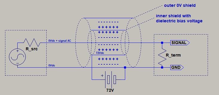
This is derived directly from the patent (US7872195), showing the second variety as per section "summary" on page 3.
I think it would "work" more effectively if they have used a single isolated wire in U form accross the whole cable length, connected in series with a resistor and then applied to "72" DCV battery. It would draw small current (defined by resistor resistance value) continuously, thus creating constant magnetic field and acting like a shield from external EM noise induction.
Just my thoughts, don't judge strictly
Just my thoughts, don't judge strictly
OP
- Thread Starter
- #131
It is simple and that is why it does nothing.This is derived directly from the patent (US7872195), showing the second variety as per section "summary" on page 3. And it is really straightforward.
No it doesn't. The signal wire is in the center with nothing from the battery hooked up to it. So it is not riding on top of anything. Company says so itself:With DC bias the electrical field undergoes a large fixed DC potential with the AC riging on top of it which result in only a strength change (really small in terms of percentage) of the field, whereas in a standard coax the field generated by the signal voltage changes strength and direction, the latter being claimed the culprit, dissipating energy.
What you are saying is what operates on the insulation, not what operates on the signal wires. It is the insulation that sees the DC static charge and AC induced field. These effects on the insulation are negligible.
Jimster480
Major Contributor
What else is new.... most everything I have seen from AudioQuest is just a money lifting joke. This is even worse than Schiit
KSTR
Major Contributor
You guys crack me up ;-)Thanks for schematic. I see that 72V circuit is not closed because of very large resistance of dielectric material, and AFAIK an open voltage does not create any magnetic field. Current must be passing to create a field around it.
This is about pre-polarizing a dielectric, which requires an electric field, not a magnetic field.
Well, we just don't know if any effects on the dielectric are neglegible.What you are saying is what operates on the insulation, not what operates on the signal wires. It is the insulation that sees the DC static charge and AC induced field. These effects on the insulation are negligible.
Note that the shown schematic is functionally 100% identical to a scheme where the center conductor would actually carry a DC voltage, which would require DC blocking caps at both ends and a high value feed resistor to apply the DC with a source impedance high enough to not load the AC source. The identity is easy to spot: The center conductor and the shield layer next to it are a different DC potentials and thus create the electrical field to pre-polarize the dielectric.
I do understand that electrical charges can be accumulated between the two dielectrics as they're supplied from the battery source, but do not understand how field can be generated between the center signal wire and the shield layer next to it, they are completely two different sources/circuits.The identity is easy to spot: The center conductor and the shield layer next to it are a different DC potentials and thus create the electrical field to pre-polarize the dielectric.
Which confirms that it will do nothing against external EM noise induction.This is about pre-polarizing a dielectric, which requires an electric field, not a magnetic field.
P. S. I think I can forward my suggestion from previous post to AudioQuest for their next product inspiration
CelticAudioGnome
Member
- Joined
- Jan 29, 2022
- Messages
- 45
- Likes
- 11
"Wait, my cable batteries are empty!"
DonR
Major Contributor
Pay particular attention to the section Guidelines for Applying Electrostatic Shields
Nor the moon phase. I think we're back to sighted listening here.He didn't tell us the room temperature either. Shameful.
Amir looked 160dB down. Not even your phono cartridge signal is that tiny.View attachment 73883
This is derived directly from the patent (US7872195), showing the second variety as per section "summary" on page 3. And it is really straightforward.
With DC bias the electrical field undergoes a large fixed DC potential with the AC riging on top of it which result in only a strength change (really small in terms of percentage) of the field, whereas in a standard coax the field generated by the signal voltage changes strength and direction, the latter being claimed the culprit, dissipating energy.
I will repeat that I do not defend the specific cable or manufacturer nor will I say such a dielectric bias will reduce whatever distortion in a normal line-level interconnect or speaker cable but for phono MM or MC cables, where source impedance is high and signal levels are low, it could be possible that these very low-level effects could be strong enough to be a) easily measured and b) they might be potentially audible. I don't believe much in cable sound but phono cables are the only place where I ever noted a hint of a difference...
Similar threads
- Poll
- Replies
- 493
- Views
- 52K
- Poll
- Replies
- 187
- Views
- 36K
- Poll
- Replies
- 52
- Views
- 11K
- Replies
- 1
- Views
- 350
- Poll
- Replies
- 138
- Views
- 20K
G