Could they be modulator idle tones? I don't know enough about the inner working of common converter modulators to offer more than speculation, but in SDM based frequency synthesizers I have seen similar kinds of level and input dependent behavior particularly when DC or periodic inputs are supplied.FWIW, it seems I've found a phenomenon with the AK4490 (of my RME Adi-2 Pro FS) that might be some form of noise-floor modulation. Between around -30dBFS and -50dBFS I see an increase of harmonics and mirrored harmonics in the upper frequency range. If one were to factor in these in a wideband THD (sans noise) measurement we would have a mid-level THD rise (not unlike the ESS chips) even when the low components stayed completely the same, because at higher levels the HF components get lower and lower in level and get spread out in frequency range, and at lower levels they get shifted higher and higher in frequency, hence making less of a contribution. Actually, only a hint of H2 was visible, and always lower in level than this new dirt.
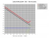
See attached plot, a loopback measurement (348kHz SR, 512k FFT, 32 averages). Shown is a 300Hz signal at levels from -34dBFS to -42dBFS. Traces have been separated by 10dB for visibility, center trace has no offset. ADC runs at 20dB gain to eliminate its influence (DAC level +24dBu, ADC level +4dBu). ADC is not the culprit, double checked with analog generator (Tek SG505). Things do *not* depend on sample rate. With other rates than 384kHz used here only the right side of the plots is truncated, otherwise no change. Frequency also doesn't matter much (and don't need to be bin-centered. If it's not a bin-center, FFT needs window which raises processing noise floor). With higher freq the spacing gets wider and the onset of the mirrored components is more readily visible (see below). Wider spacing means less total energy, therefore the effect is worse at lower frequencies.
The really interesting thing is that the error spectra get heavily shifted around in frequency, especially the start of the error components, with rather moderate level changes of 2dB.
Also, we can see at -42dBFS the needles are all equally spaced at 300Hz intervals. At the higher levels, as second train of needles appears in the right-hand area of the plots which are 300Hz-spaced, but not on 300Hz multiples -- looks like mirrored at the sampling frequency (clearly visible when zoomed in and/or using higher test freq).
Those tones I saw can actually go way below 20kHz with some combinations of frequency and level, so it doesn't seem AKM did some form of shaping to have those tones strictly above the audio band, or at least it is not fully effective.
Not shown, I made further observations: If the test signal is not a pure sine, components start to reduce quickly. Even when a second tone (of arbitrary frequency, but preferably lower and unrelated) is 60dB down to the main tone, the hash disappears. DC level send to the DAC matters as well (which puts the modulator into a different operating point), as soon as the DC is higher than ~ -30dBFS, the needles go away).
Of course, all the dirt is way below RMS noise floor, also we don't have 100% pure sine content in any music, so it's possibly completely inaudible... but actually we don't know...
View attachment 30501
(also posted on DIYaudio.com a few days back)

-
WANTED: Happy members who like to discuss audio and other topics related to our interest. Desire to learn and share knowledge of science required. There are many reviews of audio hardware and expert members to help answer your questions. Click here to have your audio equipment measured for free!
You are using an out of date browser. It may not display this or other websites correctly.
You should upgrade or use an alternative browser.
You should upgrade or use an alternative browser.
Audio measurement gear
- Thread starter Mivera
- Start date
Could they be modulator idle tones? I don't know enough about the inner working of common converter modulators to offer more than speculation, but in SDM based frequency synthesizers I have seen similar kinds of level and input dependent behavior particularly when DC or periodic inputs are supplied.
Idle tones are also a function of activity level- the more the activity and the more random it is the smaller the tones tend to be.
As a result random dither is used, with some success, to break up idle tones. One possibility to assess the cause might be to add more dither, if possible, to the test input, and see if there is any effect.
Not particularly surprising. The same thing occurs with synthesizers. It's likely a consequence of the intrinsic modulator designs. I believe that audio converter designs are generally higher order than 2, which reduces the idle tone behavior substantially, but I also believe that some pattern dependent short term limit cycles can be produced, and not just with a DC input, and this measured effect seems to be similar to what I would expect if that were the case.Dither has no effect on this. Unless you add so much noise that it can't be called dither anymore and seriously degrades the chip's performance.
I know that in the synthesizer world we experienced similar issues and as a result built in a limit cycle detection algorithm that was intended to flag a problem and perturb the modulator when such events occurred. Of course, the scenario was not necessarily comparable as we had minimum spur amplitudes and other noise specs that were quite different from an audio requirement.
In any case, it's likely that the converter SDM design team is aware of the problem, but it's not an issue that can be readily fixed retroactively.
Do the latest generations of converters demonstrate the same effects? I know that it was implied that it was a general problem, but is that totally the case?
KSTR
Major Contributor
Well, it looks like it's really a limit cycle issue and not noise floor modulation as I had speculated. I found a good paper on this and from skimming through it (with my rather limited knowledge in this field) I gather that low-level input stream dither doesn't help much, only detection and corresponding action of injecting a small pertuberance, or alternatively, periodic injection without detection.
With any normal music or other real-world signal an audio DAC will probably never encounter conditions what will trigger limit cycles but with pure sines used for measurements it will. I would think the audio DAC designers are aware of the problem but choose to ignore it because it's 99.99% irrelevant. OTOH, the paper states that limit cycle detection and destruction does not need that much resources and almost doesn't impair specs...
With any normal music or other real-world signal an audio DAC will probably never encounter conditions what will trigger limit cycles but with pure sines used for measurements it will. I would think the audio DAC designers are aware of the problem but choose to ignore it because it's 99.99% irrelevant. OTOH, the paper states that limit cycle detection and destruction does not need that much resources and almost doesn't impair specs...
Yes, that's the paper that we used as a basis for attempting to correct limit cycle issues that we experienced in a synthesizer.
Alas, it didn't work perfectly- there were other cycles that popped up that were less problematic. It's definitely a whack a mole type situation.
Alas, it didn't work perfectly- there were other cycles that popped up that were less problematic. It's definitely a whack a mole type situation.
By the way, I'm still busy evaluating the softwares.
I'm busy testing Multi Instrument Automation API.
What do you think of following trend ?
My goal is to show when the distortion kicks-in and is above the noise (here in a TI PCM4222EVM ADC test)
(Note: I used a temporary setup, so this may not be representative of actual board performance)

or better this one, maybe

In the second one, we see what I suspect is some DAC-involved distortion raise above -2dB (since we see the same for RME loopback)
I'm busy testing Multi Instrument Automation API.
What do you think of following trend ?
My goal is to show when the distortion kicks-in and is above the noise (here in a TI PCM4222EVM ADC test)
(Note: I used a temporary setup, so this may not be representative of actual board performance)
or better this one, maybe
In the second one, we see what I suspect is some DAC-involved distortion raise above -2dB (since we see the same for RME loopback)
Last edited:
Just done the test again, with higher DAC output range, to reach 0dBFS on the ADC

Note that the noise is (a hair) LOWER than the RME, which is impressive !
Max input level is +19dBu-3.5 = +15.5dBu = 4.6Vrms
Distortion is obviously not coming from the DAC at that level (since the RME loopback at same level is way better)
(RME ADI-2 Pro fs in loopback is the reference, but it doesn't reach 0dBFS here, since the PCM reaches 0dBFS before)
Last edited:
Its in the datasheet ")
Keep the input level below -20dBFS

Keep the input level below -20dBFS
Well, if we limit to +4dBu, then I can switch the RME input to +4dBu range, and the picture becomes a bit different.
That's one of the strengths of the RME: Both input and output may be swicthed to another range.
First same picture than above, but with RME DAC using balanced output at +13dBu
RME ADC range set to +19dBu

Then when I switch the ADC range of the RME (and, of course, the test's Maximum level) to +4dBu

That's one of the strengths of the RME: Both input and output may be swicthed to another range.
First same picture than above, but with RME DAC using balanced output at +13dBu
RME ADC range set to +19dBu
Then when I switch the ADC range of the RME (and, of course, the test's Maximum level) to +4dBu
Well looks to me like it behaves as the data sheet indicates with distortion rising above - 18dBFS.
Your levels still seem a bit higher than my experience with the board though. I do remember the idle noise level was around - 122dB (A weighted) so that's around - 120 flat.
Just check the idle noise floor and a 1khz - 60dB signal and see if it matches up with the plots in the data sheet.
Your levels still seem a bit higher than my experience with the board though. I do remember the idle noise level was around - 122dB (A weighted) so that's around - 120 flat.
Just check the idle noise floor and a 1khz - 60dB signal and see if it matches up with the plots in the data sheet.
Last edited:
Well, indeed, it looks like I miss last 3dB.Well looks to me like it behaves as the data sheet indicates with distortion rising above - 18dBFS.
Your levels still seem a bit higher than my experience with the board though. I do remember the idle noise level was around - 122dB (A weighted) so that's around - 120 flat.
Just check the idle noise floor and a 1khz - 60dB signal and see if it matches up with the plots in the data sheet.
And as the RME trend shows, it's not a DAC-side limitation of the measurement.
Are you summing/averaging both channels to get this figure ?
The -60dB, you see it in the graph. That's close to -117dB flat.
- Joined
- May 15, 2019
- Messages
- 872
- Likes
- 3,615
That was a wasted like. So far zamiraty contributed 4 posts that consist only of quotes and copies of statements from others at the begining of the respective thread - no own content. Here from post #2. Typical spammer behaviour...
Good catch. He is history.That was a wasted like. So far zamiraty contributed 4 posts that consist only of quotes and copies of statements from others at the begining of the respective thread - no own content. Here from post #2. Typical spammer behaviour...
- Joined
- May 15, 2019
- Messages
- 872
- Likes
- 3,615
We could do the digital part, but not the analog one. You would be forced to split your input signal and apply it to both input channels. Therefore we have no plans to add such a feature, sorry.
Yes, of course I'd split the analog signalWe could do the digital part, but not the analog one. You would be forced to split your input signal and apply it to both input channels. Therefore we have no plans to add such a feature, sorry.
Last edited:
Well, indeed, it looks like I miss last 3dB.
And as the RME trend shows, it's not a DAC-side limitation of the measurement.
Are you summing/averaging both channels to get this figure ?
The -60dB, you see it in the graph. That's close to -117dB flat.
No it wasn't summed. I have actually broken the board I had a while. I dropped a screwdriver on it
Basically the data sheet doesn't exaggerate, it's 108dB thd + n at - 1dBFS.
audio_tony
Addicted to Fun and Learning
Am I missing something from that article?
The THD seems unexpectedly high for those devices?
Similar threads
- Replies
- 85
- Views
- 7K
- Replies
- 8
- Views
- 533
D
- Replies
- 1
- Views
- 683
- Replies
- 9
- Views
- 2K
- Replies
- 5
- Views
- 547