For science...
Thanks to the measurements from Amir, combined with some additional info from Erin, I was able to figure out how the actual level trimming circuit is designed.
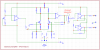
The used AD5262 is basically a 20k0 controllable 'potmeter' but instead of a wiper there are electronic switches (which add the distortion measured Amir.)
There is a datasheet from the chip which shows the roll-off from the chip (only 20kΩ trace is relevant)
This roll-off is caused by an internal 55pF capacitance in the chip itself.
At 20kHz the chip itself (no attenuation = 99 setting) rolls-off -0.05dB (40kHz = -0.1dB)
This will be a bit worse at -1dB (90 setting).
The chip itself has (close to) 0.025dB 'steps' internally. The AVA box has 0.1dB trim level steps which means 4 'resistor steps' are used for each 'trim level step' resulting in a 312Ω 'trim level step' in the 20kΩ potmeter.
Below the schematic as is present inside the AVA box. That is excluding the relays used for routing the input signals. These will not change anything.
Turns out it was not just the AD5262 (which was evident from Amir's dashboard) but has 2 additional resistors and the output resistance measurements from Amir.
The tricky part was finding out which values were used and Erin provided that additional data.
It's a good thing these resistors were added as it makes the box a bit less input and output resistance dependent in the first trimming level settings.
But is also creates some issues (roll-off differences). These are caused by the cable (and load) capacitance combined with the output resistance of the circuit.
That roll-off frequency, however, is also load resistance dependent.
This resistance differences has consequences and also explains why there is discrepancy between Amir's and Josh's measurements (100k load vs 50k load)
Of course the source resistance also has a small influence on the output R but is too small to make changes in the frequency response.
Simulation time ... in Multisim I simulated the AD5262, the source output resistance, the circuit itself, the load resistance and cable capacitance.
Not knowing what RCA cables were used I measured some of my cables and on average these were close to 200pF/meter.
So .. I simulated using 1m and 2m cables and with source resistance of 100Ω and for the load I simulated 100kΩ (APX555), 50kΩ (Josh's amp), 10kΩ and as some would like to see what would happen with a 2kΩ load.
Influence of the source resistance in relation to the output resistance was also simulated 0Ω, 20Ω, 100Ω, 600Ω and 2kΩ.
Lets start with the output resistance (valid for DC-10kHz) and simulated for setting 99 and 'worst case' 90 setting. This would mean the output voltage difference between the DACs should not be apart more than 1dB (about 10%). If DAC A is 2.0V out (dBFS) the other DAC should be between 1.8V and 2.2V
When that difference would be more things will change. Going by the remark from Josh that the trimming always fell within the 90-99 range.
The change in output resistance of the AVA box is marginally source resistance.
Most DACs will be between 100Ω and 600Ω out and this will not change the roll-off in an audible way.
Then we also have the question what the DAC's in question see as a load.
Of course, this also changes for different loads and different trimmer settings.
Below the load the DAC sees when the AVA box is loaded with a specific resistance. No load, 100k load, 50k load, 10k load and 2k load at trim levels 99 and 90.
Here we can see that the load the DAC sees changes a bit depending on the load which, dependent on the output R of the used DAC will result in slightly different levels at best. When using a 50kΩ load (Josh) and assuming a DAC has a 600Ω Rout (likely worst case scenario) calculates as max. 0.02dB level difference.
So now the FR changes (simulated) using 1m RCA at the output (the input cable is not relevant) and a 2m cable with different load resistance in 99 and 90 trim.
There is a little snag though which is the load resistance matters and as the DACs were level matched at the output of the amp this requires the 'trim setting' to be different from 90 with a lower load impedance.
The frequency response thus is simulated in 99, 90 and (-1.1dB attenuation level) with 1m and 2m RCA cable and given at 1kHz and 20kHz only.
This means that the box as used by Josh, depending on the cable capacitance (which is unknown) can have a max. frequency deviation of around -0.13dB at 20kHz.
When a 1m cable was used around 0.03dB deviation (which jives with Josh's measurement).
Safe to say the AVA box was unlikely to cause an audible roll-off difference.
Phase in worst case @ 20kHz was 10° but most likely just a few degrees at most.
This does not invalidate any of Amir's measurements as it is unknown what cable capacitance was used and a higher load resistance was used (100k) than what Josh used so the few measurements Josh made seem to be correct.
In the end... For me, the roll-off, load and source resistance for 90 and 99 trim seems to jive with the measurements and in Josh's case thus do not appear to be as bad as Amir's measurements show (on this particular aspects) because of the different conditions tests were done.
Also note: these were just simulations and are likely close to reality but can differ.
Now... while the roll-off and phase differences in Josh's case do not appear to be an issue that does in no way mean the box is O.K. and usable for critical listening comparisons.
Reasons are the substantial distortion that, acc to Josh's measurements, differ per trimming will nullify any differences in DACs due to distortion (profiles) of the compared DACs as the distortion of the AVA box is magnitudes higher and will mask any differences.
Level matching may have been within 0.05 and 0.15dB (we have no clue).
There is crosstalk between A and B input.
There can be timing differences between DACs giving cues.
In the end... is the AVA box the best method to compare DACs that are very similar (but arguably not the same) in performance?
Not by a long shot.
There is NO way to tell what Josh heard and what was the actual cause of the tests. Sadly only recordings of the actual tests would have shown the reasons for the results.
The evidence simply is not there and means the results are clear but may not have been between the DACs and could well have been caused by the (poorly performing) AVA box.
This much is clear from Amir's measurements.