• Welcome to ASR. There are many reviews of audio hardware and expert members to help answer your questions. Click here to have your audio equipment measured for free!

Audio by Van Alstine ABX Comparator Review

And lest we forget, the other showstopper is the AVA distortion and noise. No way, no how should he have proceeded if he knew that it added so much junk to the signal. Why does any subjectivist believe that he is really hearing the differences between DACs when the pathway is so unclean? Folks there don't trust a cable to be transparent. Now this box is???
 
other showstopper is the AVA distortion and noise
@amirm is the AVA distortion and noise sufficient to mask the DACs’ distortion and noise rather than just affect both DUTs identically?

My conclusion is this problem plus the level matching issue is the best explanation for Josh’s results. I just don’t think anyone could get 110/112 comparing DACs where differences would be minuscule at most without an interfering factor.
 
Last edited:
Whatever amount it is, I'm sure it's nominal. People make their hobbies pay a little all the time. Rarely more than the money they put into the hobby.
 
@amirm is the AVA distortion and noise sufficient to mask the DACs’ distortion and noise rather than just affect both DUTs identically?
Very much so. Distortion levels are too low and at any rate, are masked. What is not masked is the noise level. In the past, I have fed very low level signals to DACs, then boosted them in software. I am talking 40 to 50 dB. There, you can hear the difference in background noise. What this translates to is that with sufficiently loud amplification, you may be able to hear the same.

Now apply the AVA to that. Its noise is so loud that you would go deaf hearing it relative to background noise of the DAC!

When I tried to compare two DACs with AVA, in quiet parts there was massive amount of ground loop noise as I mentioned that was varying to boot so more noticeable.

If we are talking about adding 10% noise to what is there, sure. But that is not even technically possible as these DACs are already state of the art as far as noise. Some clock as low as -140 dB! So low that I can't even measure them with my analyzer.

As you can tell from my answer, I am motivated to find audible differences if they exist in DACs. If this box could help with that, I would be all in. But it is so bad, so embarrassingly bad, that no credible case can be made that you can hear any DAC's impairments through it, let alone differences with another DAC.

 
My conclusion is this problem plus the level matching issue is the best explanation for Josh’s results. I just don’t think anyone could get 110/112 comparing DACs where differences would be minuscule at most without an interfering factor.
Exactly. I give it 99% odds that the levels were not properly matched. The last 1% would be the ever so slight frequency response differences which may have gotten worse with the AVA in the loop.
 
Also, I don't know how he accurately measured levels in REW. REW/Cosmos combo does not have a volt meter (unlike proper audio analyzers like AP). You would have to go by pixels shown in a graph which can be prone to errors given the small voltage differences we are talking about.
You have to calibrate to make it a voltmeter, but REW does give precision levels allowing for good relative measurements. It bounces around with pink noise but still good enough for 0.1dB. With a sine wave it is rock solid with 0.01 precision with the default display. Below is with VB Cable so perfect but even with the 43V input on the Cosmos it should do just fine for 0.1 dB matching.
1791707004959.png
 
You have to calibrate to make it a voltmeter, but REW does give precision levels allowing for good relative measurements.
But you can't calibrate it. At least not easily. The displayed values if based on FFT are subject to significant error due to window function and spectrum bleed. Without it, you can easily be off more than 0.1 dB.
 
@amirm
RMS across any selected frequency range (like 20Hz-20kHz or whatever you want) is shown automatically in REW. Depends only on operator knowledge and skills.
Excellent for calibration.

Edit: for those who would not notice at first glance. Peak FFT value is -12dBV, which is 251mV. However, rms value over 22kHz is 401mV. And A-weighted is 410mV for the reason that A-weight curve slightly adds level to midband frequencies.

cassette_GPO_1kHz.wav.png
 
Last edited:
  • Like
Reactions: rjp
But you can't calibrate it. At least not easily. The displayed values if based on FFT are subject to significant error due to window function and spectrum bleed. Without it, you can easily be off more than 0.1 dB.
But for comparative purposes it would all be the same for A and B wouldn't it?
 
But for comparative purposes it would all be the same for A and B wouldn't it?
Sure. Not speaking about the fact that members scarcely use high-quality true rms DMM, not mentioning calibration. This is again a nit-picking.
 
Sure. Not speaking about the fact that members scarcely use high-quality true rms DMM, not mentioning calibration. This is again a nit-picking.
FWIW worth my DMM is B+K true RMS. But it is 30 years old and hasn't been calibrated in quite a while!
 
I don't think calibrating with REW using dB units is the right way.

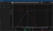
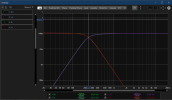
Example, exact same measurements, fully calibrated REW in terms of voltage and gain, Voltage vs dB, look at the voltage difference when only 0.1dB is the difference:


dB.PNG Voltage.PNG
 
I don't think calibrating with REW using dB units is the right way.

Example, exact same measurements, fully calibrated REW in terms of voltage and gain, Voltage vs dB, look at the voltage difference when only 0.1dB is the difference:


View attachment 563774 View attachment 563775
Not even for sine waves? REW got my -12dB sine wave exactly right. The sine wave generator in REW would not have used any kind of FFT or anything to compute its level, just an attenuation of full scale values, right?
 
Not even for sine waves? REW got my -12dB sine wave exactly right. The sine wave generator in REW would not have used any kind of FFT or anything to compute its level, just an attenuation of full scale values, right?
That's 4M sweeps you see there, just after calibrating levels using sines at 12 frequency points using dB units for the 4 channels measured there (2 channels Low+2 channels Mid-High)
Using voltage units and sines on the other hands gets you exactly where it should if you check with the same sweeps right after it.

(ok we're talking about 0.3mV-1.3mV differences here, but still...)
 
Last edited:
That's 4M sweeps you see there, just after calibrating levels using sines at 12 frequency points using dB units for the 4 channels measured there (2 channels Low+2 channels Mid-High)
Using voltage units and sines on the other hands gets you exactly where it should if you check with the same sweeps right after it.

(ok we're talking about 0.3mV differences here, but still...)
I think this is more complex than we need to get into. Josh used pink noise and a 1KHz sine wave. I am setting aside the noise because that is not as good for this. Do you really think his 1KHz relative level measurement for A and B would be off?
 
I think this is more complex than we need to get into. Josh used pink noise and a 1KHz sine wave. I am setting aside the noise because that is not as good for this. Do you really think his 1KHz relative level measurement for A and B would be off?
It depends how and what he used for it.

As much as I can see here testing a gazillion of ways, there's simply no way to match levels at exact (and I mean exact) voltages (=levels) across the spectrum if the slightest FR change occurs between them.

And that's not only this box's fault, it just makes it way worse than it already is if FR changes exist.
 
Back
Top Bottom