• WANTED: Happy members who like to discuss audio and other topics related to our interest. Desire to learn and share knowledge of science required. There are many reviews of audio hardware and expert members to help answer your questions. Click here to have your audio equipment measured for free!

Audio Buffer – unity gain link stage/headphone amp with ultimate output drive capability

MC_RME

Addicted to Fun and Learning
Technical Expert
Audio Company
Joined
May 15, 2019
Messages
871
Likes
3,613
Measuring low level audio with a DSO is mostly impossible. You should try to use a powerbank or other battery to get the ADI from the grid, then you might see less of these effects. Using the bandwidth limit feature is also a must, but for audio it is typically still much too high (20 MHz...).
On my own DSO I see these effects at highest sensitivity even when I short the probe itself.
 
Last edited:
OP
pma

pma

Major Contributor
Joined
Feb 23, 2019
Messages
4,602
Likes
10,769
Location
Prague
Noise output of my RME ADI-2 PRO fs, measured with Siglent SDS 1202X-E DSO

The DAC is connected via USB to the PC I'm using right now. Volume is off (one step below-96.3 dB), Samplerate 44.1 kHz, no audio signal playing.

Unbalanced Out
Yellow=left channel, pink = right channel, 100us/div, 10 mV/div:

Oops - spikes and RF pulses. Lets increase sensitivity to 2mV/div:

Yep. Lets zoom in to the RF pulse in the middle (2 us/div):

Let's zoom in more and measure its frequency (20ns/div):

With the cursors covering 10 wavelengths the frequency is 10 times as displayed = 68.3 MHz, level left channel ~5mVpp..

Let's look at one of those short spikes:

That's a ringing pulse. Zoom in to measure its frequency:

Frequency is around 180 MHz.

I'm not sure what to make of this. Is it a measuring artifact? Do i measure something wrong?

XLR out (right channel)

I measure both signals against ground and use the math function of the DSO to show the difference. The noise was much higher :oops: so I started with 2ms/div and 20 mV/div:

The level of the difference is 40 mVpp and quite lower than the singular signals. When we zoom in (5 us/div) we find only spikes at a distance of 14.4 us (repetition rate 69 kHz):

Zoom in to the spike in the middle (50 ns/div) :

It's an RF pulse, 87 MHz at 40 mVpp.

Side Notes
All results are independent of volume and output reference level. Pulling the USB connection has no influence either.

Since I bought it not only for music but also for measurements I'm a bit puzzled what to think about this. Maybe I do something wrong. I'd like @MC_RME to have a look and correct any failures I've possible done.

I'm sure nothing of this is audible at all; the frequencies are much too high and will be swamped in the first stage of any audio amplifier if it reaches them in the first place. But for measuring high gain amplifiers like phono or microphone preamplifiers you are well advised to set the DAC to a high output voltage and use a voltage divider to create the desired input level; just using a volume of -50 dB will give you a nice low level signal but it will be swamped by those high frequency noise and spikes and I don't think this to be a valid input signal for measureing those preamps.

A small advice, that you probably know - have a scope supplied from isolation transformer with lowest possible primary/secondary capacitance. Preferably use a battery supplied notebook for USB connection.

Now about RME - a guy here had horribly destroyed the RME ADI when he connected it to one of the recommended power banks. He sent the unit to the manufacturer and got it repaired, for some fee, though it was under warranty still. OK. Difficult to argue in such cases.

He brought me the power bank and the original RME AC adapter for measurements. I didn't find anything wrong with the power bank and even initial turn-on transient and load-change transient were OK, at 12V, with short 200ns spike at 19V.

1576584200115.png


The original AC adapter output spectrum was nothing to call home about and IMO worse than that of the power bank
1576584297692.png
 

raindance

Major Contributor
Joined
Sep 25, 2019
Messages
1,040
Likes
971
My Siglent scope introduces far too much HF noise and pulses to be any use at all for noise measuring.
 

LTig

Master Contributor
Forum Donor
Joined
Feb 27, 2019
Messages
5,816
Likes
9,535
Location
Europe
Measuring low level audio with a DSO is mostly impossible. You should try to use a powerbank or other battery to get the ADI from the grid, then you might see less of these effects. Using the bandwidth limit feature is also a must, but for audio it is typically still much too high (20 MHz...).
On my own DSO I see these effects at highest sensitivity even why I short the probe itself.
You are absolutely right. I finally adapted the AUTOK cable I had bought some time ago to an old Panasonic LC-R123R4PG rechargeable sealed lead battery (used for several years to feed a DIY 10W 12V light for my bicycle until LED light came of age). I connected it to the ADI-2 PRO and connected its TRS outputs with RG58 cables to the DSO. Although the DAC was not yet powered on I saw the same RF pulses and spikes on the DSOo_O, so I disconnected the battery and still the DSO showed the same rubbish: :facepalm:

power_off_noise_TRS-out_L+R.png


Same with XLR out:

power_off_noise_XLR-out.png


So this rubbish definitely is not produced by the ADI-2 PRO at all.

I have to apologize that I did not make this specific check before posting. I had checked that with the cables shorted the rubbish disappeared and therefore thought that the DSO would be OK. But I stand corrected and am really thankful for this - I'm still used to analog scopes and trusted the DSO too much (Wer misst misst Mist). Of course I'm very happy that my ADI-2 PRO is perfectly usable for audio measurements.

I'm going to edit my first posting now to make sure the reader knows that these measurements are plain wrong.
 
Last edited:

LTig

Master Contributor
Forum Donor
Joined
Feb 27, 2019
Messages
5,816
Likes
9,535
Location
Europe
The next 2 plots show how the Audio Buffer reduces HF noise and spikes present at the output of the DacMagic Plus D/A converter:

View attachment 42606

View attachment 42607

This clearly shows that though the Audio Buffer has wide bandwidth (300kHz), it greatly reduces HF stress and reduces possibility of SR input limitation in the amplifier that follows behind the DAC (or the CD player).
May I suggest to repeat these measurements with the DAC powered off? As I have learned today you cannot trust a DSO at all when measuring low level signals.
 

MC_RME

Addicted to Fun and Learning
Technical Expert
Audio Company
Joined
May 15, 2019
Messages
871
Likes
3,613
Just wanted to post that ...:)
 
OP
pma

pma

Major Contributor
Joined
Feb 23, 2019
Messages
4,602
Likes
10,769
Location
Prague
May I suggest to repeat these measurements with the DAC powered off? As I have learned today you cannot trust a DSO at all when measuring low level signals.

Yes you may but this has been done as a 1st thing during the original measurements session. This is not the thing I have learned today ;). Not only to power off the DAC - I test the measurement setup ON, DAC ON, measuring cable or probe tip connected to its shield and this connected to body of RCA DAC output. Capacitive current flow through the measuring cable shield and there must be no or little interference. This basic system error measurement is then compared to the signal measurement result. Measuring had been my profession, before I retired.
Plots shown above were measured on power supplies, as I declared.

1576654805837.png


BTW, Klaus @KSTR made a nice job on shield interference voltages and it is posted even here at ASR

https://www.audiosciencereview.com/...-in-unbalanced-audio-interconnects-pdf.21753/
 
Last edited:
OP
pma

pma

Major Contributor
Joined
Feb 23, 2019
Messages
4,602
Likes
10,769
Location
Prague
Headphone amplifier

I have some news - I have removed the R10 output series resistor (see http://pmacura.cz/buffer_en.html ) to get the lowest output impedance, as is dictated by contemporary trends. The output impedance is now 0.0559 ohm and the circuit is stable, which makes it pretty competitive when compared to anything in the market. Output power to 32ohm is more than 1W. To make some comparison, I have ordered AN-1768 LME49600 Headphone Amplifier Evaluation Board from TI, see
http://www.ti.com/lit/ug/snaa052a/snaa052a.pdf
This TI board was issued in 2008, 5 years after I published the Audio Buffer and it is almost the same circuit, including LME49600 buffer, which is in fact the same circuit as that much older Burr Brown BUF634T.
So I am interested in comparison results, the eval. board is expected to arrive on January 3. I will write a review then.

1577719786008.png
 
Last edited:

pozz

Слава Україні
Forum Donor
Editor
Joined
May 21, 2019
Messages
4,036
Likes
6,827
Headphone amplifier

I have some news - I have removed the R10 output series resistor (see http://pmacura.cz/buffer_en.html ) to get the lowest output impedance, as is dictated by contemporary trends. The output impedance is now 0.0559 ohm and the circuit is stable, which makes it pretty competitive when compared to anything in the market. Output power to 32ohm is more than 1W. To make some comparison, I have ordered AN-1768 LME49600 Headphone Amplifier Evaluation Board from TI, see
http://www.ti.com/lit/ug/snaa052a/snaa052a.pdf
This TI board was issued in 2008, 5 years after I published the Audio Buffer and it is almost the same circuit, including LME49600 buffer, which is in fact the same circuit as that much older Burr Brown BUF634T.
So I am interested in comparison results, the eval. board is expected to arrive on January 3. I will write a review then.

View attachment 44045
Any news about this next review?
 
  • Like
Reactions: pma
OP
pma

pma

Major Contributor
Joined
Feb 23, 2019
Messages
4,602
Likes
10,769
Location
Prague
Any news about this next review?

Yes, but no good news, unfortunately. I ordered the evaluation board from this link
https://www.ti.com/store/ti/en/p/product/?p=LME49720NABD

and was believing to receive the 49720+49600 board, as listed also here
https://www.ti.com/tool/LME49720NABD

However, I received this
1578248692365.png


which only contains the LME49720. So unfortunately, no headphone amp to test. It seems that TI website description of eval board is not very clear, at least to me. There is also no documentation for the board that I received. I had to find it in the old LM4562 datasheet. I did not want to complain, but as you are asking, this is as it goes.
 

pozz

Слава Україні
Forum Donor
Editor
Joined
May 21, 2019
Messages
4,036
Likes
6,827
Yes, but no good news, unfortunately. I ordered the evaluation board from this link
https://www.ti.com/store/ti/en/p/product/?p=LME49720NABD

and was believing to receive the 49720+49600 board, as listed also here
https://www.ti.com/tool/LME49720NABD

However, I received this
View attachment 44712

which only contains the LME49720. So unfortunately, no headphone amp to test. It seems that TI website description of eval board is not very clear, at least to me. There is also no documentation for the board that I received. I had to find it in the old LM4562 datasheet. I did not want to complain, but as you are asking, this is as it goes.
That's really too bad (from a business perspective too, for TI; disorganization is a poor sign).
 
OP
pma

pma

Major Contributor
Joined
Feb 23, 2019
Messages
4,602
Likes
10,769
Location
Prague
I only have some more measurements on my Audio Buffer from this thread, so maybe a "review" of it later. I measured e.g. output HF spectrum and was very happy with the result.

1578250564524.png
 
OP
pma

pma

Major Contributor
Joined
Feb 23, 2019
Messages
4,602
Likes
10,769
Location
Prague
Headphone amplifier

I have some news - I have removed the R10 output series resistor (see http://pmacura.cz/buffer_en.html ) to get the lowest output impedance, as is dictated by contemporary trends. The output impedance is now 0.0559 ohm and the circuit is stable, which makes it pretty competitive when compared to anything in the market. Output power to 32ohm is more than 1W.

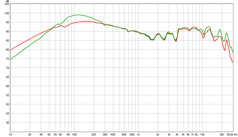
After doing some listening tests I have to say that Sennheiser HD598 headphones sound much better and much more accurate with the audio buffer output impedance lowered to almost zero, and it probably makes sense, when I look at Innerfidelity mesurements:

1578603129178.png


Before I had a 50 ohm output series resistor in the audio buffer and it must have made some difference.
 

miero

Active Member
Joined
Aug 1, 2018
Messages
241
Likes
292
Why was 50Ohm resistor there? To prevent oscillations into capacitive load? Will the buffer be stable also if you use your dummy speaker load?
 
  • Like
Reactions: pma

solderdude

Grand Contributor
Joined
Jul 21, 2018
Messages
16,004
Likes
36,220
Location
The Neitherlands
120-ohm-r1.png


HD599 (similar to 598) driven from 0.2 and 120 Ohm.
With 50 Ohm you would have an audible bump in the lows (making it muddier)
 
OP
pma

pma

Major Contributor
Joined
Feb 23, 2019
Messages
4,602
Likes
10,769
Location
Prague
Why was 50Ohm resistor there? To prevent oscillations into capacitive load? Will the buffer be stable also if you use your dummy speaker load?

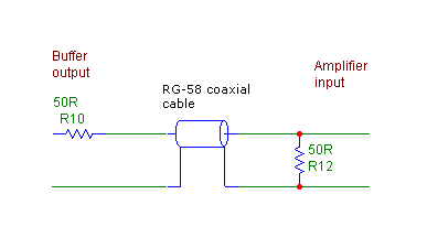
Because originally it was a link stage and the worst HF scenario for the coax cable (re HF interference capture and reflections) is to drive it from zero impedance and to load it with infinite impedance (10kohm or infinite is no difference). So the series output resistor (R10 below) reduces reflections and interferences, because the cable is sourced from Zw and not from 0. Optimum (HF) would be termination at both sides like
bufcab.gif

but R10 is enough to get just a single reflection.

With headphones, R10 is pointless and R10=0 is best for damping. Yes, the circuit is stable into complex and capacitive load but not every opamp is usable then. I run it with AD744 and it is stable.
 
OP
pma

pma

Major Contributor
Joined
Feb 23, 2019
Messages
4,602
Likes
10,769
Location
Prague
With 50 Ohm you would have an audible bump in the lows (making it muddier)

Exactly, that's how it sounded with 50 ohm compared to 0 ohm. However, no ABX, same level request is violated if shorting the 50 ohm ;) :D
 

solderdude

Grand Contributor
Joined
Jul 21, 2018
Messages
16,004
Likes
36,220
Location
The Neitherlands
You could still do it this way (though pointless) if you add a series RCL circuit in parallel to the load exactly couteracting the impedance hump and RC to equalize the treble rise in the impedance. In which case you could also make this headphone current driven.

The HD598 is designed to be voltage driven though.
 
  • Like
Reactions: pma
OP
pma

pma

Major Contributor
Joined
Feb 23, 2019
Messages
4,602
Likes
10,769
Location
Prague
One more point to cable termination, which is considered useless for audio.

1) RG58 driven from audio buffer with zero output impedance and terminated by 1 Mohm (scope). This is the worst scenario, cable shorted input, open output:
0_1Mohm_sq.png

Small signal, resolution 2mV/div, wideband measurement

2) better scenario, driven from zero output impedance but terminated with 50 ohm at the end
0_50ohm_sq.png

Please note much less HF noise at top and bottom of the square.

The same you will see even with zero input signal, cable with shorted input and open output is just prone to HF noise due to endless reflections, though small in amplitude.

Edit: 210kHz square enables much more precise reading of rise time and fall time. (Generator rise time is 8ns.). Cable again terminated by 50 ohm.
0_50ohm_200ksq.png
 
Last edited:
Top Bottom