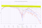
The waveguide on the other hand though increases the distance between the two mid drivers above the optimally half wavelength even when crossed as low which can be seen by the compromised vertical directivity plots.
View attachment 556645
It is still better than most typical other pseudo D'Appolitos and many other non-concentric designs but the compromise should be mentioned.
Just for the technically interested here is an example of an innovative and impressive design with wide horizontal and very narrow vertical raditation:
A bit longer answer.
Yes all that math is understood since the whitepaper from Mithat Konar
https://www.birotechnology.com/articles/VSTWLA.html.
Elliptical waveguides and chamfered woofers (mounting rim) help to reduce CTC spacing as does a low fx for the tweeter but then you need a tweeter that has enough linear volume displacement (4* more for 1k vs 2k). If you want, you can use math to simulate the nulls for different vertical angles.
The engineering goal is to first define an overall suppression level (along with frequency range) for early reflections and design the CTC that corresponds with the important directivity angles for early reflections in the targeted listening room (spec). This is very similar to how directional microphones are designed for consumer products.
We still must appreciate what problem the MTM solves, now (C8C, or similar) an MTM with low fx tweeter crossover frequency and strong vertical directivity control, placed in a normal room more strongly resembles the studio recording listening environment, aka intent of the artist. It will obviously sound closer to what the original mix was in a home environment.
If we apply a proper reasoning on how we use loudspeakers in a normal living room, we will find that DI control is actually quite good for such a small loudspeaker (these are not JBL M2 size) and the obsessions around directivity nulls as feature instead of a -6dB threshold 75% soundpower reduction) have not helped the MTM since D'Appolito presented this.
The main discussion/obsession should be around the amplitude reduction of the strongest room reflections that dominate the listening experience in home or semiprofessional settings to resemble how a well-engineered studio room sounds and looks (placement).
If we look at early reflection mitigation (acoustic equivalent of optical splatter) of this MTM the ceiling reflection is already ~6dB down for most midrange and treble (assuming around +45 degree for ceiling angle) and the floor response is equally 6dB down when using a heavy carpet. So the sidewall reflection (>60 horizontal angle desired at least with a 7" woofer pair, it can be controlled by the speaker listening location wall and distance if the room is large enough.
The front wall (relative to speaker) reflection in home listening situation must be looked at. If there is ample of space between the listener and the wall behind him/her then there is nothing needed like in a normal recording studio (the ones. If this wall is close to the listener head (e.g. <1.5m) some local absorbers will get rid of the last remaining distracting early reflection.
There we can preserve the spatial information of the original recording much better in our own listening/living rooms.
The tonal issues of speakers in the different settings will not be resolved as we have after all these years of spinorama measurement no industry standard in room target curve for home hifi and obviously no standard how a home listening room should look like. The content producing side uses a different set of target curves then the home speaker mfg. The "quasi" recording standard (X curve and Dolby Atmos Music) and everything in-between are misaligned with the -0.7dBoctave in room curve (simplified Harman curve) or all Harman curves for their product lines (untrained, average and trained listeners). When listening to various modern produced music content I found that the Dolby Atmos Music steady state room curve is likely the one that is most relevant today, the headphones and earbuds set the target for render reproduction. Needless to say, that the biggest discrepancy is <200Hz.
Lastly, it would be nice to see an ME RL901K measured here for comparison.

Would like to know the source of that signal.