• WANTED: Happy members who like to discuss audio and other topics related to our interest. Desire to learn and share knowledge of science required. There are many reviews of audio hardware and expert members to help answer your questions. Click here to have your audio equipment measured for free!

Akabak questions and problems

bigjacko

Addicted to Fun and Learning
Joined
Sep 18, 2019
Messages
722
Likes
360
Hi all to people that are interested in simulation! I don't see much thread talking about the wonderful program Akabak. I think we can create a thread talking about the tips and tricks of it, and some problems we encounter.

One question I have is the interface in front of infinite baffle. According to appendix of infinite baffle, we need to make the volume in front of a cone into another subdomain for Green's function to work. I have simulated a few scenarios and get different directivity results. The cone diameter is 0.2m. The direcitvity plots are all normalized.

For only one driver.
1 driver with protruding interface.JPG1 driver with flat disk interface.JPG1 driver with bigger than cone interface.JPG
Here are three scenarios, first is protruding interface, second is flat disk interface, third is protruding but bigger than cone.
Here are three directivity outcomes, which one is correct?
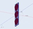
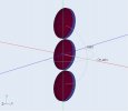
1 driver with protruding interface dir.jpg1 driver with flat disk interface dir.jpg1 driver with bigger than cone interface dir.JPG

For 3 drivers.
3 driver with 3 interface.JPG3 driver with 1 big interface.JPG
First picture have two scenarios, one is 3 drivers with 3 subdomain and 3 interface, two is 3 drivers with only 1 subdomain and 1 interface. Second picture is 3 drivers with 1 interface bigger than cone.
Here are the results, first picture is horizontal directivity, second picture is vertical directivity.

3 drivers with 3 subdomain and 3 interface
3 driver 3 sub int 3 interface hor dir.jpg3 driver 3 sub int 3 interface ver dir.jpg

3 drivers with only 1 subdomain and 1 interface
3 driver 1 sub int 1 interface hor dir.jpg3 driver 1 sub int 1 interface ver dir.jpg

3 drivers with 1 interface bigger than cone
3 driver 1 sub int 1 big interface hor dir.jpg3 driver 1 sub int 1 big interface ver dir.jpg
Which one is correct?

I have noticed that 3 drivers with 3 subdomain and 3 interface has very similar horizontal directivity to 1 driver with same size but protruding interface.1 driver with protruding interface.JPGSo is this the correct way to do infinite baffle simulation?


Another problem I have is I can't simulate the mesh files I have imported in. I have tried very easy shape like the interface above, which runs fine, but the complex shape for the cone does not run. The error code is "size zero in component"size 0 error code.JPG

No matter I use 2d surface or 3d solid, the errors are the same. The solving status is here.solving status.JPGWhat is the problem?

Thank you guys for helping out!
 

Attachments

  • 3 driver with 1 big interface.JPG
    3 driver with 1 big interface.JPG
    32.1 KB · Views: 66
  • 3 driver with 3 interface.JPG
    3 driver with 3 interface.JPG
    30.9 KB · Views: 63

Trdat

Addicted to Fun and Learning
Forum Donor
Joined
Sep 6, 2019
Messages
968
Likes
397
Location
Yerevan "Sydney Born"
The program plus the concepts are above me but thanks to Akabak's simulations the variety of drivers available with simulation/directivity plots is awesome. Helps us DIY'ers choose drivers and match directivity thanks to those who use the program and post their simulations. Hopefully, this thread picks up and gives insights to new drivers and there plots.
 
OP
B

bigjacko

Addicted to Fun and Learning
Joined
Sep 18, 2019
Messages
722
Likes
360
The program plus the concepts are above me but thanks to Akabak's simulations the variety of drivers available with simulation/directivity plots is awesome. Helps us DIY'ers choose drivers and match directivity thanks to those who use the program and post their simulations. Hopefully, this thread picks up and gives insights to new drivers and there plots.
Thanks for your words, I really hope more people can jump into here and have a great discussion here.:)
 

fluid

Addicted to Fun and Learning
Joined
Apr 19, 2021
Messages
694
Likes
1,198
All of the interfaces should produce the same result, except they do not. There is no right or wrong in the shapes or method's you showed although none of them really look like they are giving the right answer to me.

Infinite baffle is a special case because there must be a separation of in front and behind. I normally try and use as few interfaces as possible for this reason but sometimes they are necessary.

AKABAK like ABEC before it is picky about the types of mesh it will import. Gmsh version 2 is safe, as is STL.

Everything is red because none of those things have been solved. Without a mesh that works nothing can happen.
 

348montesa

Member
Joined
Feb 24, 2022
Messages
5
Likes
0
Fluid, which V2 of Gmsh? Any of the 2.x?

If you see this: could you post your geometry/mesh settings in Gmsh, and indicate in which range you move according to size and frequency simulated? I am interested in simulating horns...

I have read that it is a good practice to avoid for AKABAK to do re-meshing, can you describe your strategy here? (I try to start with a fine mesh and setting the mesh settings in akabak (global/mesh) large, ie 300hz or so (I also wonder if selecting Delaunay or Bifurcation there, but the point is I think to try to avoid it in akabak)

I have made good progress but I have still much to learn, specially to get to the point to be able to be more or less confident of the results with Akabak.

I am using v4.11 of gmsh, and 0.3 for the size factor (meshadapt) " "4" in Compute element sizes from curvature. I would also like to know if there is a way to section the surface before importing it it to gmsh and getting to have finer meshes in some surfaces (towards the throat and parts with the highest curvature, buy I don"t know of a way to do this and have compatible transitions).

For me the horn interface is giving trouble too. The horns I am simulating have a non-coplanar mouth end, so I am doing what is shown below and I feel that this is making the computations to be much longer.

1690758565249.png
 

fluid

Addicted to Fun and Learning
Joined
Apr 19, 2021
Messages
694
Likes
1,198
Fluid, which V2 of Gmsh? Any of the 2.x?
I should have said ASCii version 2 which you can select by using the export command.
If you see this: could you post your geometry/mesh settings in Gmsh, and indicate in which range you move according to size and frequency simulated? I am interested in simulating horns...
Unfortunately they change every time, each waveguide needs something different. If the surface is small I will hit it with a brute force fine mesh when it gets bigger it is harder and more time consuming to get right sometimes curvature works on it's own from 6 to 12, sometimes I need to define size at points or use transfinite curves.
I have read that it is a good practice to avoid for AKABAK to do re-meshing, can you describe your strategy here? (I try to start with a fine mesh and setting the mesh settings in akabak (global/mesh) large, ie 300hz or so (I also wonder if selecting Delaunay or Bifurcation there, but the point is I think to try to avoid it in akabak)
Basically setting the mesh resolution lower in AKABAK than the resolution of the imported mesh will do it.
I would also like to know if there is a way to section the surface before importing it it to gmsh and getting to have finer meshes in some surfaces (towards the throat and parts with the highest curvature, buy I don"t know of a way to do this and have compatible transitions).
In 3D CAD you can split the model with planes at various points and these splits will stay in the step file, you can then define each surface with a separate mesh size but that gets time consuming to do manually. If you create a .geo script they can be edited as a text file which makes changes easier.
For me the horn interface is giving trouble too. The horns I am simulating have a non-coplanar mouth end, so I am doing what is shown below and I feel that this is making the computations to be much longer.
I usually try and avoid interfaces if I can and simulate everything as External. That is another cut and try approach, I have found that making the interface like a large halo around the outside with enough space can work, but it chews a lot of mesh elements.

attachment.php
 

348montesa

Member
Joined
Feb 24, 2022
Messages
5
Likes
0
Thanks Fluid!. Mostly like I am doing it. Your example pic is just like I've been doing it (you are showing a solid horn + surface for the interface). I should loft in three steps (and not like in the pic below) as this leads to less mesh elements. Do you bring the solid body to gmsh, or just the surface? I only import surfaces in gmsh.

I would like to try without interfaces, but the few times I tried I didn't have success. If you hat any tips here please help, I am using thousands of elements in the interface alone... Only exterior domain with both horn and driving surface elements (w/ fixed drive)?

I asked about meshing in Akabak (avoiding it) because even with a fine mesh from gmsh and large mesh setting in akabak, I have the feeling (starting each simulation) that Akabak might be remeshing, as it does not skip that first step completely anyway.

I have split the surfaces with Fusion, but I think (i might be wrong thou) that the mesh has to be done in such a way that all triangles at the edge of two adjacent surfaces have to match their vertices (i.e you can't have one triangle at one side with a vertex at the midpoint (for example) of the adjacent triangle on the other surface. By the way, is there a quick way to re-associate surfaces with akabak domain elements? If one for example has a project and one finds that the mesh has to be redone, is there a quick way to associate a new msh file to the subdomain/interface elements? The way I do it is that I delete all the domain elements and re-define them, but this is time consuming. If the number/list order of re-meshed surfaces is the same, it would be nice to find a quick method.

One more thing I would like to ask is about your observation settings. I have struggled sometimes with radiation imp. Sometimes it does only show a flat line, while the polar map seems ok. I have never been able to get a rad. imp. graph like shown on the ATH thread (perhaps w/ heavy smoothing). How about DI index graph w VACS? ATH is so nice as it saves so much time, but I am interested in geometries I am defining through python scripts and I wouldn't know how to arrive at them there (if even possible).


1690762999831.png


1690765051851.png
 
Last edited:

fluid

Addicted to Fun and Learning
Joined
Apr 19, 2021
Messages
694
Likes
1,198
Thanks Fluid!. Mostly like I am doing it. Your example pic is just like I've been doing it (you are showing a solid horn + surface for the interface). I should loft in three steps (and not like in the pic below) as this leads to less mesh elements. Do you bring the solid body to gmsh, or just the surface? I only import surfaces in gmsh.
If you want to use the interface make it in flat planes as much as possible then you won't waste elements on curvature, also the more uniform the triangles are the better the simulation solves for a given resolution. Sometimes I use a solid body but mostly surfaces, if it is solid you have to select only the outside surfaces anyway.
I would like to try without interfaces, but the few times I tried I didn't have success. If you hat any tips here please help, I am using thousands of elements in the interface alone... Only exterior domain with both horn and driving surface elements (w/ fixed drive)?
You need a rear enclosure surface of some kind otherwise at some point the mesh will be infinitely thin, you really need that anyway unless you are using an infinite baffle which would be hard with your waveguide shape. Fixed drive divide by jw is what I use for constant acceleration.
I asked about meshing in Akabak (avoiding it) because even with a fine mesh from gmsh and large mesh setting in akabak, I have the feeling (starting each simulation) that Akabak might be remeshing, as it does not skip that first step completely anyway.
It never skips that step.
I have split the surfaces with Fusion, but I think (i might be wrong thou) that the mesh has to be done in such a way that all triangles at the edge of two adjacent surfaces have to match their vertices (i.e you can't have one triangle at one side with a vertex at the midpoint (for example) of the adjacent triangle on the other surface. By the way, is there a quick way to re-associate surfaces with akabak domain elements? If one for example has a project and one finds that the mesh has to be redone, is there a quick way to associate a new msh file to the subdomain/interface elements? The way I do it is that I delete all the domain elements and re-define them, but this is time consuming. If the number/list order of re-meshed surfaces is the same, it would be nice to find a quick method.
I'm not sure exactly what you mean, but I often use a project as a base template by leaving the elements in place and just changing the mesh or gmsh surfaces they need to be.
One more thing I would like to ask is about your observation settings. I have struggled sometimes with radiation imp. Sometimes it does only show a flat line, while the polar map seems ok. I have never been able to get a rad. imp. graph like shown on the ATH thread (perhaps w/ heavy smoothing).
There isn't much to it, perhaps it is a driving problem.
Rad Imp.png


Rad Imp1.png


How about DI index graph w VACS? ATH is so nice as it saves so much time, but I am interested in geometries I am defining through python scripts and I wouldn't know how to arrive at them there (if even possible).
DI is possible but painful. You need a specific set of oberservation scripts to match the weights of the part spherical surface being used.

I have attached translated instructions from Nils Ollerer below.
 

Attachments

  • Buendelungsmass in VACS en-US.pdf
    354 KB · Views: 66

Elias Wiedner

Member
Joined
Jan 15, 2024
Messages
8
Likes
0
Hey Guys,

the stuff your doing is way more complicated then my questions. Im a Student and had the luck to get my hands on a Version of Akabak. I want to Simulate a Bassreflex enclosure.
Screenshot (1).png


That is the Inner Subdomain with a Rectangular hole in the baffle and all Normals Pointing inwards.

Screenshot (2).png


That is the outer Subdomain with the hole aswell and all Normals Pointing outwards.
If I now want to insert the Port. Do i do it with an extra Duct? And in which Subdomain does it belong? Or is the Vent an extra Subdomain?
And lets say i add an Interface (still dont know exactly why it needs the interface but seems like Akabak needs it to run the calculations) I will need 2 Interface Areas right? One which connects inside to the Vent and one which connects the Vent with the Outside. Both of the Interfaces have to face Inwards. Thats what i have seen in one of the 2 Videos i found in the Internet.

Thanks in Advance and sorry for my stupid questions, but the Programm seems a little intimitating to me

Elias
 

ctrl

Major Contributor
Forum Donor
Joined
Jan 24, 2020
Messages
1,632
Likes
6,232
Location
.de, DE, DEU
Or is the Vent an extra Subdomain?
And lets say i add an Interface (still dont know exactly why it needs the interface but seems like Akabak needs it to run the calculations) I will need 2 Interface Areas right? One which connects inside to the Vent and one which connects the Vent with the Outside. Both of the Interfaces have to face Inwards.

Yep, the vent as extra subdomain, two interfaces separating the areas (inner cabinet and "outside") and normals inverts.

Everything is correct, a very good result for a beginner ;)
 

Elias Wiedner

Member
Joined
Jan 15, 2024
Messages
8
Likes
0
Hey ctrl,

thx for your fast reply and also for your kind words :D If you say "normals invert" you refer to the normals of the blue interface area i guess? So where do the blue areas have to point towards? And another thing which came to my mind.
I did everything with a wall thinkness so far. If i insert a single duct as vent now it will probably lead to problems since it is infinitely thin right? Is there an easy way to make it have a certain thickness? Or do i go with 2 ducts and connect them somehow at the end(inside the enclosure) of the port.

Thx again and ill try everything tonight or tomorrow morning :)
 
OP
B

bigjacko

Addicted to Fun and Learning
Joined
Sep 18, 2019
Messages
722
Likes
360
Hey ctrl,

thx for your fast reply and also for your kind words :D If you say "normals invert" you refer to the normals of the blue interface area i guess? So where do the blue areas have to point towards? And another thing which came to my mind.
I did everything with a wall thinkness so far. If i insert a single duct as vent now it will probably lead to problems since it is infinitely thin right? Is there an easy way to make it have a certain thickness? Or do i go with 2 ducts and connect them somehow at the end(inside the enclosure) of the port.

Thx again and ill try everything tonight or tomorrow morning :)
The interface blue side is inside.

I am not expert like fluid or ctrl, but I think infinite thin port is not a problem for simulation. The only problem is box has to be altered slightly when you make the box in real life.

Making two duct and connect will be the best for real life dimensional accuracy.
 
Last edited:
OP
B

bigjacko

Addicted to Fun and Learning
Joined
Sep 18, 2019
Messages
722
Likes
360
Oh BTW I did some mid range bandpass with port. I only have one int and ext subdomain. I put interface on the outside of port. The result is surprisingly good, very close to reality. I haven't bothered trying to put another int subdomain and another interface to see if there is improvement.
 

Elias Wiedner

Member
Joined
Jan 15, 2024
Messages
8
Likes
0
Hey bigjacko,

Here i created the rectangular vent plus the Material thickness of 1.9mm. The outer subdomain is Invisible right now. Is there an easy way how i can use the front of the Vent Duct as interface or do i have to do it with nodes? Its hard to find the exact points in space which match with the rectangular ventface.
Screenshot (4).png


I think it would be a good decision to do the modeling in a CAD software right?

greets

Elias
 
OP
B

bigjacko

Addicted to Fun and Learning
Joined
Sep 18, 2019
Messages
722
Likes
360
Hey bigjacko,

Here i created the rectangular vent plus the Material thickness of 1.9mm. The outer subdomain is Invisible right now. Is there an easy way how i can use the front of the Vent Duct as interface or do i have to do it with nodes? Its hard to find the exact points in space which match with the rectangular ventface.
View attachment 342278

I think it would be a good decision to do the modeling in a CAD software right?

greets

Elias
You can use any way you want, as long as there is mesh covering the hole. Using CAD to do the whole design is another good idea.

If you can't have a duct with two closed end, maybe try making two duct with one closed end.

I just found that some of my mid compression model will need two interface at the two sides of the port. So I think in the end the best practice is to do the formal way using two interface.
 

Elias Wiedner

Member
Joined
Jan 15, 2024
Messages
8
Likes
0
Thank you for the constructive Help :) im About to Model everything in Fusion 360 right now. As soon as i have this step done ill import in Akabak and try to simulate. Ill let you know about the results. Maybe there is something interesting for you aswell.
Im kinda scared, that i wouldnt even notice if something in the simulation is wrong due to my to little knowledge about how it should look like. But i think my best bet is trial and error like all of you have probably done aswell.
 
Top Bottom