Shefffield
Member
Hello forum,
Not sure if I am in the right section or should have posted in DIY...
I need some help in designing and building some fixed ratio attenuators for my speaker setup. Digitally controlled active speaker, each driver on its dedicated DAC and amp channel.
Recently I damaged a tweeter by accidentally putting out full power after a mis-click in Totalmix FX. It is possible to deactivate the functionality "double click toggles -infinity dB/zero dB", but after a Windows crash this somehow got deactivated. Scratch one ribbon tweeter, thanks Microsoft!
So my challenge is to solder some attenuators to limit the maximum level I can torture my drivers with. It also won't hurt to not use too much digital headroom for the volume control and to be able to keep the virtual fader around -10..-30 dB instead of -50..-70, to pick just any numbers.
I am still learning electronics and would feel much more confident in actually building and connecting anything after some checking by you.
Signal source:
RME Fireface UFX II
 rme-audio.com
DA Line Out 3-8 switchable:
+4 dBu: 1,227 V RMS / 3,472 V peak to peak
-10 dBV: 0,316 V RMS / 0,894 V peak to peak
Maximum output level: +19 dBu (6,903 V RMS / 19,526 V p-p)
Output impedance: 75 Ohm
Connection: 6,3 mm TRS jack, servo-balanced
(Calculator used for the conversion to volts: http://www.sengpielaudio.com/calculator-db-volt.htm)
Signal sink:
Powersoft D-Cell 504
Amplifier gain: 32 dB (x40 voltage gain)
Input sensitivity @ 8 Ohm: 0,94 V / 1,7 dBu
Maximum input level: 4,36 V / 15 dBu
Input impedance: 10 kiloOhm balanced
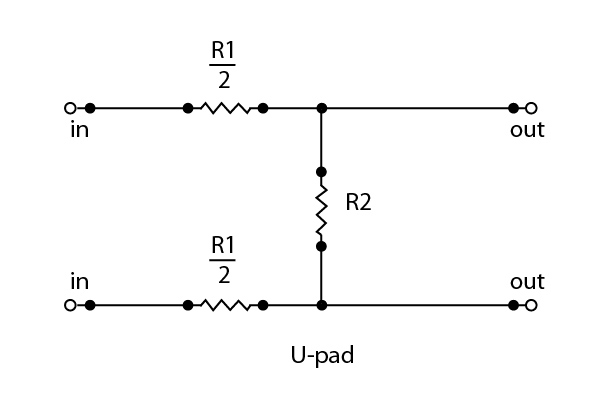
First question: T-pad or H-pad?
I found these schematics and calculators:
 mh-audio.nl
I'm going to use balanced connections, so I'll have to make identical attenuator circuits for 2 and 3, right?
I think the most elegant solution is to build a few attenuators in plugs, with different fixed levels, so I can run my tests and measurements and chose the matching attenuation by simply swapping plugs. However, TRS plugs needed for the UFX II don't have any spare room, and the D-Call modules have shrouded header connectors. Any recommendations for inexpensive, but reliable connections I could use here?
Thank you in advance,
Axel
Not sure if I am in the right section or should have posted in DIY...
I need some help in designing and building some fixed ratio attenuators for my speaker setup. Digitally controlled active speaker, each driver on its dedicated DAC and amp channel.
Recently I damaged a tweeter by accidentally putting out full power after a mis-click in Totalmix FX. It is possible to deactivate the functionality "double click toggles -infinity dB/zero dB", but after a Windows crash this somehow got deactivated. Scratch one ribbon tweeter, thanks Microsoft!
So my challenge is to solder some attenuators to limit the maximum level I can torture my drivers with. It also won't hurt to not use too much digital headroom for the volume control and to be able to keep the virtual fader around -10..-30 dB instead of -50..-70, to pick just any numbers.
I am still learning electronics and would feel much more confident in actually building and connecting anything after some checking by you.
Signal source:
RME Fireface UFX II
Fireface UFX II - RME Audio Interfaces | Format Converters | Preamps | Network Audio & MADI Solutions
RME Audio Professional Live, Studio, Recording and Broadcast Solutions. Unrivalled Quality, Performance & Stability MADI Interfaces, Converters & Preamps.
rme-audio.com
DA Line Out 3-8 switchable:
+4 dBu: 1,227 V RMS / 3,472 V peak to peak
-10 dBV: 0,316 V RMS / 0,894 V peak to peak
Maximum output level: +19 dBu (6,903 V RMS / 19,526 V p-p)
Output impedance: 75 Ohm
Connection: 6,3 mm TRS jack, servo-balanced
(Calculator used for the conversion to volts: http://www.sengpielaudio.com/calculator-db-volt.htm)
Signal sink:
Powersoft D-Cell 504
Amplifier gain: 32 dB (x40 voltage gain)
Input sensitivity @ 8 Ohm: 0,94 V / 1,7 dBu
Maximum input level: 4,36 V / 15 dBu
Input impedance: 10 kiloOhm balanced
First question: T-pad or H-pad?
I found these schematics and calculators:
Voltage Divider Calculator
I'm going to use balanced connections, so I'll have to make identical attenuator circuits for 2 and 3, right?
I think the most elegant solution is to build a few attenuators in plugs, with different fixed levels, so I can run my tests and measurements and chose the matching attenuation by simply swapping plugs. However, TRS plugs needed for the UFX II don't have any spare room, and the D-Call modules have shrouded header connectors. Any recommendations for inexpensive, but reliable connections I could use here?
Thank you in advance,
Axel