• Welcome to ASR. There are many reviews of audio hardware and expert members to help answer your questions. Click here to have your audio equipment measured for free!

A Pneumatic Loudspeaker Experiment Traveling Through Time: How Would You Measure It?

DeltaSignum

Member
Joined
Sep 4, 2026
Messages
39
Likes
8
Hello everyone,

A quarter of a century ago, I built a 10-inch experimental loudspeaker based on an unusual pneumatic concept. The project was eventually left behind because of a combination of technical limitations and economic priorities.

In 2026, a series of coincidences brought the idea back to my attention. Rather than rebuilding the old 10-inch system, I deliberately reduced the concept to an inexpensive 2-inch laboratory model. It is not intended to be a finished loudspeaker - its purpose is to make the pneumatic behaviour easier to investigate and measure, while keeping the experiment inexpensive and easy for others to reproduce.

200-2026.jpg


Around 2000 I had access to a well-damped recording/post-production studio, which gave me a useful environment for this kind of experimentation.
The tools available today are remarkably accessible compared with what I remember. The problem is, I'm still a man from the past. Perhaps this community can help me bridge that 25-year gap.
 
Isn't this all done using lasers these days? by the big players at least!
 
What behaviour specifically do you want to measure?

Just the driver? The frequency response? Distortion?

How does this speaker work differently?

The original goal was to investigate whether pressure and fluid dynamics could be used to extend useful behaviour below the driver's free-air Fs while suppressing unwanted resonances, avoiding the unwanted artifacts of conventional sealed and bass-reflex enclosures.

That is why I'm interested in measuring not only the driver itself, but the complete system:
-the driver in free air
-the driver in the small enclosure with the pneumatic coupling, with particular attention to the region below the driver's free-air Fs
-the same system measured in a normal listening room
Depending on the level of detail you want, you can send it to a lab for measurement or use a measuring microphone at home and gating in REW, which will give accurate but smoothed data down to a few hundred Hz. REW is especially good for in-room measurement since you can manipulate parameters as you need. https://www.roomeqwizard.com/

The Dayton DATS will make electrical measurements and provide TS parameters and impedance for the driver in free air: https://www.daytonaudio.com/product/1650/dats-v3-computer-based-audio-component-test-system Dayton also has a Loudspeaker Analyzer system which can do large signal testing: https://www.parts-express.com/DATS-LA-Loudspeaker-Analyzer-390-805?quantity=1

At home I use REW with a calibrated Earthworks M30 (good for high SPL and accurate): https://earthworksaudio.com/measurement-microphones/m30/ And an SPL calibrator: https://www.reedinstruments.com/product/reed-r8090-sound-level-calibrator
 
Depending on the level of detail you want
Thanks for the suggestions.

I don't plan on going back to pro audio after all these years, so there isn't much point in investing in a full measurement lab. If the project becomes interesting to others, that's another matter. And I don't yet have a proper impedance measurement of the complete system - that is one of the next things I want to establish with the sound-card/reference-resistor method.

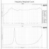
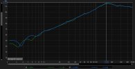
Acoustically, I have nearfield measurements taken about 2 cm from the cone with the pneumatic boundary OPEN and CLOSED. The purpose was not to obtain an absolute LF response, but simply to compare the two boundary conditions under otherwise identical conditions. Fs ~160

open_closed.jpg

What interests me is that closing the final pneumatic opening does not appear to produce the straightforward transition I would expect if the system were behaving simply as a conventional vented enclosure becoming sealed.

For the low-frequency response of the complete system, my other measurements were even more basic - essentially 1/0 logic: is there a measurable response or not.

At this stage I'm mainly looking for advice on which measurements would best distinguish classical enclosure resonance effects from the behaviour of the pneumatic structure itself - which is what the original experiment was intended to investigate.
 
At this stage I'm mainly looking for advice on which measurements would best distinguish classical enclosure resonance effects from the behaviour of the pneumatic structure itself - which is what the original experiment was intended to investigate.
In this case it would be the impedance measurement of the driver in free air vs. an enclosure. Although the latter might be a little noisy if there are leaks in the edges, speaker gaskets, etc.
 
Very interesting post, unfortunately I don't feel very qualified to chime in on what measurements ought to be performed beyond the usual - SPL/frequency, distortion/SPL/frequency, and so on.

If you haven't checked out DIYAudio.com yet, it's mostly focused on speaker building and some of the folks there are also pretty sophisticated about measuring the parameters of speaker enclosures and drivers. Some are here too, but this forum is more oriented toward finished products than parts, if that makes sense. :)
 
DIYAudio.com
I'm familiar with it. The question is not whether conventional measurement methods exist, but whether they are appropriate for this particular architecture. If the implementation is indeed unconventional, it may require a different measurement approach, otherwise, conventional methods can produce misleading results.
 
I'm familiar with it. The question is not whether conventional measurement methods exist, but whether they are appropriate for this particular architecture. If the implementation is indeed unconventional, it may require a different measurement approach, otherwise, conventional methods can produce misleading results.
High-resolution frequency response measurements across a range of angles are effective, but are not practical in most nonprofessional circumstances, particularly at the low frequencies you are interested in.
 
I assume vibrating air interacts with surfaces and they can be measured with lasers, but I'm not sure what you get by measuring the 'pneumatic system' - can you explain what this is about?
 
I'm familiar with it. The question is not whether conventional measurement methods exist, but whether they are appropriate for this particular architecture. If the implementation is indeed unconventional, it may require a different measurement approach, otherwise, conventional methods can produce misleading results.
I guess it's hard for me to say, not only because I am not an engineer as some folks here are, but because I don't understand how the penumatic system works or interacts with the speaker cone / cabinet. I will say the graph you posted looked pretty interesting in terms of how the response falls off, but without more information on the mechanism it's hard to say how to go about evaluating it.
 
At this stage I'm mainly looking for advice on which measurements would best distinguish classical enclosure resonance effects from the behaviour of the pneumatic structure itself - which is what the original experiment was intended to investigate.
The near field measurement looks more than competent to me. It shows a picture book response of a sealed box (2nd order high pass) with f_s ≈ 140Hz and Q ≈ 1.1
However, the difference between open and closed is microscopic at best. I do not know what the “pneumatic structure“ is supposed to do, but it does not seem to do a lot of it.
I do not think that the problem is in measuring.
 
Last edited:
Hello everyone,

A quarter of a century ago, I built a 10-inch experimental loudspeaker based on an unusual pneumatic concept. The project was eventually left behind because of a combination of technical limitations and economic priorities.

In 2026, a series of coincidences brought the idea back to my attention. Rather than rebuilding the old 10-inch system, I deliberately reduced the concept to an inexpensive 2-inch laboratory model. It is not intended to be a finished loudspeaker - its purpose is to make the pneumatic behaviour easier to investigate and measure, while keeping the experiment inexpensive and easy for others to reproduce.

View attachment 556410

Around 2000 I had access to a well-damped recording/post-production studio, which gave me a useful environment for this kind of experimentation.
The tools available today are remarkably accessible compared with what I remember. The problem is, I'm still a man from the past. Perhaps this community can help me bridge that 25-year gap.
I can only imagine vaguely what a "unusual pneumatic concept" may look like.
You may explain that concept so all can understand what it is in priciple?
 
A laser would show us exactly what the diaphragm is doing. But would it show us what the entire pneumatic system is doing?
I don't really understand what you trying to do, and may be you can elaborate more on the details. But if you want to have a more complete view of the acoustic field, Microflown makes acoustic particle velocity probes (not cheap). They let you measure the 3-D acoustic particle velocity vector. If you position the probe close enough to the driver diaphragm, since the acoustic particles (i.e. the air) adjacent to the diaphragm follow its movements, you can get pretty close readings of the diaphragm motion too.


Perhaps related to your idea, here is a JASA (Journal of the Acoustical Society of America) paper looking at the theoretical aspects of the rotary subwoofer by Eminent. The rotary subwoofer works not by pushing and pulling the air in front of a cone to generate sound pressure, but by creating acoustic particles (air) movements, which then translate into SPL. This method overcomes the low acoustic radiation impedance, and therefore efficiency, of loudspeaker drivers that are much smaller than the wavelength of the sound at low frequencies.
http://jpark.us/pubs/JASA_MS-08-05890_nopp_Park.pdf
 
A laser would show us exactly what the diaphragm is doing. But would it show us what the entire pneumatic system is doing?
Sounds like a job for simulation rather than measurement. Perhaps @René - Acculution.com could make some suggestions.

Although a description of the system would be a good start.
 
book response of a sealed box

Fs ≈140 Hz would actually be quite good for 2-inch driver. :) I haven't found reliable T/S data for the exact driver used here. The closest manufacturer's data I found for a similar 2-inch model (slightly different basket) specifies Fs = 158.83 Hz.

2inch_TS.jpg

Regarding the “picture book sealed box” interpretation that's interesting. Are you interpreting the ≈140 Hz feature as the system resonance (Fc) and Q ≈1.1 as Qtc?

If so, what would you expect to change when the pneumatic path is opened versus blocked?
 
If so, what would you expect to change when the pneumatic path is opened versus blocked?
As long as it is not clear, what a ' pneumatic path' is, this question is kind of not respondable.
Please offer some schematic, at least.
 
Ahmm, same question from different people.. I’m trying to start with measurements before giving a detailed interpretation, so there are fewer assumptions to argue about later.
The simplified topology is:

driver ⇄ chamber ⇄ Impulser ⇄ container ⇄ compensator ⇄ atmosphere

In the OPEN condition the final pneumatic path communicates with the atmosphere. In the BLOCKED condition that boundary is closed, while the internal geometry remains the same. The behaviour seems to depend on the previous state of the system and on changes in the input.
More details (links) are available through my profile, but for now I'm more interested in the measurements.
 
Last edited:
Back
Top Bottom