- Joined
- Jun 10, 2018
- Messages
- 6,195
- Likes
- 9,293
@ernestcarl I measured and made a wavelet spectrograph. The dotted line is smooth and flat in the crossover frequency range. Thank you for showing me this tip.

Thanks for your help.
I redid all the measurements in the same listening spot and I have measured the result of the alignment after applying the delay suggested by REW.
In the updated .mdat you can find:
1) RR left new: the new left channel measure;
2) RR sub new: the new sub measure;
3) Aligned sum from AL: the simulated aligned sum from the Alignment Tool, obtained after applying 7 cycle FDW on 1) and 2). The delay found by REW is 7.95 ms (to apply to the left channel) at 100 Hz;
4) RR left dly 7.95ms: the left channel measure after applying the 7.95 ms delay;
5) RR left dly 7.95ms + sub: the final measure with left aligned and sub.
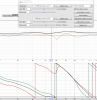
If I plot the wavelet spectrogram of the final measure 5) I have a strange behavior at about 130 Hz which I can't explain:
View attachment 136780
Have I made any mistakes during the procedure?
The behaviour isn't strange it is what happens when there is boundary interference. There is a null in time which then goes away as other parts of the room fill it in so when you look at a long time frequency plot it looks good but when you look at the spectrogram or use a Frequency dependent window it looks terrible and lumpy.If I plot the wavelet spectrogram of the final measure 5) I have a strange behaviour at about 130 Hz which I can't explain:
The sub (measured to the driver dustcap) is only about 1 meter further away from the listening position, so the remaining difference must be due to using two different model DACs for the 3 channels of the 2.1 system (and maybe the sub, an SVS SB1000 Pro, is adding some delay).
The difference in propagation delays due to DAC's is tiny and changing them won't help you. The lowpass filters can add a lot of apparent delay over and above the physical distances. Trying using the alignment tool or filtering the impulses that will give you a much better idea if the delay number is correct.
I was meaning the crossover filters that will be needed unless they are linear phase they can add a lot of apparent delay, if they were switched off then they wouldn't be the cause. The best delay setting will be found with the crossovers in place. The delay could be room interference as in the last example. Look at the spectrogram to see what is going on it's very hard to tell much at all from the graph you posted, posting a link to an mdat makes it easier for others to see what you have and offer their thoughts.
") (or maybe I didn't test it with the appropriate audio materials)
(or maybe I didn't test it with the appropriate audio materials)You can get a reasonable phase alignment between 75 and 100Hz with 6.92ms on the main speakers if a 6 cycle FDW is used. If the alignment point is moved up to 100Hz with no windowing the time blows out to 17ms due to the increased room interaction. The energy peak is delayed in the spectrogram at some point both are suffering boundary interference but at different frequencies.
Thank you very much @fluid and @ernestcarl, I learned a lot of new things! Do you have any recommended reading about all of these topics?
In the mean time I have another doubt with the above spectrogram plots below 50 Hz: as you can see, the peak energy arrives ~60 ms later than the energy above 50 Hz. Reading about the wavelet spectrogram, I saw that in an ideal plot the peak energy needs to arrive at about the same time for all the frequencies, is it correct? In my <50 Hz region the sub is 'soloist', so this 60 ms delay is due to a not ideal interaction between the room and the sub? Are our ears sensitive to these different delays in the spectrum? I also tried to do some 'blind' tests between the aligned system and the not aligned one but I couldn't hear any differences, maybe my ears are just bad
imo people are overcomplicating.
play around with rough delay jumps until you get excess group delay close to zero (use dirac impulse for audible pre-delays).
from there play around with finer delay steps until you get the flattest in the crossover region