• WANTED: Happy members who like to discuss audio and other topics related to our interest. Desire to learn and share knowledge of science required. There are many reviews of audio hardware and expert members to help answer your questions. Click here to have your audio equipment measured for free!

DIY 3D Speaker Scanner - the Mathematics and Everything Else

OP
NTK

NTK

Major Contributor
Forum Donor
Joined
Aug 11, 2019
Messages
2,707
Likes
5,969
Location
US East
Disclaimer; I havent build the system with the minidsp yet, but have experience with other multichannel systems.
The timing synchronisation between the channels is guaranteed by the xmos processor on the minidsp boards and the asio driver on the pc ( sample accurate) and if absolute time-of-flight info from the speaker to the mics is required for the calculations (is it? or can you you input the measured r?)
a loopback channel can be added.
For my current measurements that i also made with another automated matlab system, with one mic and 2 axis rotation, I dont care about the absolute time of flight, only about the time differences between all measurements.
I don't know for sure. But since the method is widely used to measure noise emitted from machines to diagnose vibration problems, and in those cases we wouldn't know what the exact "stimulus signal" is, the exact time deltas between the stimulus and measurements are likely not important. So I'd agree we only need to time synchronize the measurements.
 

Few

Member
Joined
Oct 27, 2020
Messages
91
Likes
95
Thanks for the clarification on the source used for the simulations, and for your patience with a poorly worded question. Obviously the source couldn’t be an omnidirectional point source or we could save ourselves a lot of trouble! In any case, I remain interested in ultimately determining whether different shaped surfaces suit different speaker styles. As long as a satisfactory fit is ultimately achieved, I guess it doesn’t matter, but perhaps fewer measurements can be used if they’re on an optimized surface shape?

By the way, Geddes uses more densely packed points near the speaker axis and fewer off axis, arguing that there’s typically finer directivity structure near the main axis. If that turns out to be a general rule, perhaps we don’t need the same density of points everywhere. Another opportunity to save measurement time? As I picture images of directivity that I’ve seen, I think I typically see the opposite—large frontal lobe with finer lobes off-axis. Maybe a smart system could figure out on the fly where to make densely packed measurements and where fewer are needed.

Silly cable-robot lesson learned: If you use short cables, and don’t pay attention, the cable (fishing line in my case) can completely pay out and then, even though the stepper is still moving the same direction, the line can start being withdrawn rather than released! Unspooling becomes spooling, and all the computer code instantly suffers from a sign error. Rather obvious once it’s happened. Nonetheless, I confess that I didn’t think of it before putting short pieces of line on the spindles. Longer lines are now installed. I still need to do some calibration and homing work, but the system is starting to work in a fairly sensible way. So far the line seems to wrap rather neatly on the spools even without a fancy guiding mechanism. We’ll see if that continues.
 

Few

Member
Joined
Oct 27, 2020
Messages
91
Likes
95
For my non-REW program, I found that the stimulus to-measurement timing was not stable from scan-to-scan, so a loop-back signal is necessary. So even if synchronization between the channels is handled well on one scan, it’s important that the stimulus-to-response timing is stable from sweep to sweep (meaning position to position). I’m sure you’re well aware of that, Kessito, but it may not be obvious to those who haven’t made such measurements so I’m just pointing out one of the subtleties.

I’m eager to see how the multichannel approach works. Gaining a factor of more then 10 in measurement speed would sure be welcome.

Few
 
OP
NTK

NTK

Major Contributor
Forum Donor
Joined
Aug 11, 2019
Messages
2,707
Likes
5,969
Location
US East
First step to port the code to MATLAB ...

The first problem is MATLAB doesn't come with the spherical harmonics function or the spherical Bessel and Hankel functions (unlike Python). Fortunately, the spherical harmonics function is available here:
https://www.mathworks.com/matlabcentral/fileexchange/69262-spherical-harmonics?s_tid=srchtitle

And the spherical Bessel and Hankel functions can be constructed using the formulas provided in the NIST Digital Library of Mathematical Functions (DLMF) with existing MATLAB functions, see equations 10.47.3 to 10.47.6 here:
https://dlmf.nist.gov/10.47#E1

I haven't started writing the MATLAB code for the spherical Bessel and Hankel functions yet, but for testing I managed to create a MATLAB script to "duplicate" the spherical harmonics picture in Klippel's poster.
https://www.klippel.de/products/rd-system/modules/nfs-near-field-scanner.html
csm_Sphericall_Harmonics_kleiner_cccc019ae2.png


I plot mine a bit differently from Klippel. I used the method described in the Part 1 PDF in the opening post of this thread. For example, if you compare the second row, my plot show 3 dipoles in mutually perpendicular directions. In Klippel's plot the lefthand side shapes are the same as the righthand side shapes, but with the color shading reversed.
spherical_harmonics.png

The MATLAB code is attached here. To generate the above plot, run this in the MATLAB command window:
plot_harmonicY(20)
This command will plot 21 rows as the spherical harmonics start with order 0.

Step 1 down. Many more steps to go :)
 

Attachments

  • plot_harmonicY.zip
    2.5 KB · Views: 108
Last edited:

Few

Member
Joined
Oct 27, 2020
Messages
91
Likes
95
Very pretty! Nicely done. It's even pretty quick! I think the three mutually perpendicular shapes version (the everywhere real functions) that you chose is more intuitive for this application. It makes it more obvious how they can be combined to aim the response in any desired direction.

It has always struck me as odd that Matlab has the associated Legendre polynomials but leaves it to the user to assemble the spherical harmonics out of them. They seem to be used everywhere, so why not just include them in a convenient form? In any case, I'm looking forward to seeing the other functions!

Few
 

Kessito

Member
Joined
May 18, 2020
Messages
54
Likes
99
First step to port the code to MATLAB ...

The first problem is MATLAB doesn't come with the spherical harmonics function or the spherical Bessel and Hankel functions (unlike Python). Fortunately, the spherical harmonics function is available here:
https://www.mathworks.com/matlabcentral/fileexchange/69262-spherical-harmonics?s_tid=srchtitle

And the spherical Bessel and Hankel functions can be constructed using the formulas provided in the NIST Digital Library of Mathematical Functions (DLMF) with existing MATLAB functions, see equations 10.47.3 to 10.47.6 here:
https://dlmf.nist.gov/10.47#E1

I haven't started writing the MATLAB code for the spherical Bessel and Hankel functions yet, but for testing I managed to create a MATLAB script to "duplicate" the spherical harmonics picture in Klippel's poster.
https://www.klippel.de/products/rd-system/modules/nfs-near-field-scanner.html
csm_Sphericall_Harmonics_kleiner_cccc019ae2.png


I plot mine a bit differently from Klippel. I used the method described in the Part 1 PDF in the opening post of this thread. For example, if you compare the second row, my plot show 3 dipoles in mutually perpendicular directions. In Klippel's plot the lefthand side shapes are the same as the righthand side shapes, but with the color shading reversed.
View attachment 112742
The MATLAB code is attached here. To generate the above plot, run this in the MATLAB command window:
plot_harmonicY(20)
This command will plot 21 rows as the spherical harmonics start with order 0.

Step 1 down. Many more steps to go :)

AWESOME! I have started with scaling up my matlab lab measurement code for n=x channels and had a very good conversation with an old friend of mine who is a real audio hardware/dsp guru and have him enthousiasted for the challenge "how to get 64mems mics in the pc" he had all kind of ideas (I think the coolest would be to have a A2B audio network interface in i.e. 16 channel segments and then an A2B to Dante interface so the whole system is scalable, Dante audio can get easily and cheap into any pc/mac with the Dante Virtual Soundcard https://www.audinate.com/products/software/dante-virtual-soundcard which costs only $29).
I will focus on the software first once you have done these first steps to try to find out if we can get good results with cyclindrical measurements.

To all people out there; if we would have a hardware (pcb) design and the DSP code/ Dante part covered, do any have you have the time/recources to organize to get stuf manufactured and maybe organize a group buy thing?

Cheers,
Kees
 
Last edited:
OP
NTK

NTK

Major Contributor
Forum Donor
Joined
Aug 11, 2019
Messages
2,707
Likes
5,969
Location
US East
Thanks for the clarification on the source used for the simulations, and for your patience with a poorly worded question. Obviously the source couldn’t be an omnidirectional point source or we could save ourselves a lot of trouble! In any case, I remain interested in ultimately determining whether different shaped surfaces suit different speaker styles. As long as a satisfactory fit is ultimately achieved, I guess it doesn’t matter, but perhaps fewer measurements can be used if they’re on an optimized surface shape?

By the way, Geddes uses more densely packed points near the speaker axis and fewer off axis, arguing that there’s typically finer directivity structure near the main axis. If that turns out to be a general rule, perhaps we don’t need the same density of points everywhere. Another opportunity to save measurement time? As I picture images of directivity that I’ve seen, I think I typically see the opposite—large frontal lobe with finer lobes off-axis. Maybe a smart system could figure out on the fly where to make densely packed measurements and where fewer are needed.
Sorry for misunderstanding your question and taking my time to reply. I find it usually better for me to sit on questions for a day or two to give my brain time to digest them.

Correct me if I am wrong -- I think what you are asking is if we can reduce the 3D mathematical problem into 2D. That means assuming that there is no variation in the z-direction and we can eliminate it from the model.

I think that should work well if we are using anechoic or quasi-anechoic measurements (with sound only radiating from the speaker). I am not so sure if field separation can work well. Unlike anechoic measurement in the far field where all the sound sources are close to the measurment plane, with room reflections we will have sources that are well outside of the measurement plane (for example, floor and ceiling reflections). I don't know how well 2D sound field separation will work in these cases.

I haven't looked carefully at the 2D Helmhotz equation solutions, and so at this time I don't even know how to setup mathematical model. But I'll keep thinking about it.
 

Few

Member
Joined
Oct 27, 2020
Messages
91
Likes
95
My 2D suggestion was meant more as a theoretical limiting case to test my understanding, than as a practical suggestion. We'll never have an infinitely long line source, or perfectly reflective floor and ceiling at the ends of a finite line, so the 2D approach won't see the light of day in practice. I hadn't considered the fact that even if all points on an infinite line are identical, the room reflections may vary with altitude, so that would throw a wrench into the idea. So don't waste too many neurons on the idea!
 
OP
NTK

NTK

Major Contributor
Forum Donor
Joined
Aug 11, 2019
Messages
2,707
Likes
5,969
Location
US East
My 2D suggestion was meant more as a theoretical limiting case to test my understanding, than as a practical suggestion. We'll never have an infinitely long line source, or perfectly reflective floor and ceiling at the ends of a finite line, so the 2D approach won't see the light of day in practice. I hadn't considered the fact that even if all points on an infinite line are identical, the room reflections may vary with altitude, so that would throw a wrench into the idea. So don't waste too many neurons on the idea!
Thought about it just a little bit more. I think the problem with a 2D (line) source is that distance attenuation is 3 dB/double-distance, as oppose to 6 dB/dd for a speaker in 3D far field. That, I believe, will cause distance extrapolation to not work correctly if we try to apply 2D results to 3D reconstruction.

So I don't think we can make measurements on, say, the horizontal plane only, and perform sound field separation to get high resolution FR results at the lower frequencies.
 

Few

Member
Joined
Oct 27, 2020
Messages
91
Likes
95
On the other hand, there’s no near field-far field transition, so the extrapolation (even though it’s different) should still be straightforward—maybe more straightforward.

In the completely unrealistic case of an infinite line source, with no environmental reflections that screw up the symmetry, everything is in the near field. In this made-up world, cylindrical symmetry is assumed and everything has to be consistent with it. So you can measure anywhere you please, extrapolate the results (using the lower attenuation rate characteristic of line sources) and be confident it has to work for all heights and all distances. At least that’s the way I see it (as I await an embarrassing correction). The SPL falls off more slowly than does a point source, but it’s completely predictable. So extrapolation should be no more problematic.

I think the trick is to break free from the 3D mindset for this case, embrace the cylindrical symmetry of the situation, and use it to reduce the workload. One video in the the Klippel video series I linked to many posts ago suggests something along these lines. They suggest not bothering with a bazillion measurements for line arrays. Measure one of the repeating units (they assumed a line array of dynamic drivers) and use computation to predict the result of summing many of those in a particular geometry.

But of course it’s all moot because none of us have speakers or rooms that match these conditions! It’s still interesting to ponder the limits, though.
 

Kessito

Member
Joined
May 18, 2020
Messages
54
Likes
99
I was thinking;
If it is possible to measure double cylindrical and reconstruct the coefficients from this, then the ( exact) acoustical centre could also be determined afterwards; you could simply try different heights ( different r) in the coefficients calculations afterwards and see where the optimum is in the polar plots.
Does that make any sense?

ps; could these matlab functions be of any help for the Bessel and Hankel functions?:
Bessel: https://nl.mathworks.com/matlabcentral/fileexchange/8488-spherical-besselfunctions
Hankel 1st, 2nd: https://nl.mathworks.com/help/matlab/ref/besselh.html
 
Last edited:
  • Like
Reactions: NTK
OP
NTK

NTK

Major Contributor
Forum Donor
Joined
Aug 11, 2019
Messages
2,707
Likes
5,969
Location
US East
I was thinking;
If it is possible to measure double cylindrical and reconstruct the coefficients from this, then the ( exact) acoustical centre could also be determined afterwards; you could simply try different heights ( different r) in the coefficients calculations afterwards and see where the optimum is in the polar plots.
Does that make any sense?

ps; could these matlab functions be of any help for the Bessel and Hankel functions?:
Bessel: https://nl.mathworks.com/matlabcentral/fileexchange/8488-spherical-besselfunctions
Hankel 1st, 2nd: https://nl.mathworks.com/help/matlab/ref/besselh.html
Thanks for the links to the MATLAB code for the spherical Bessel functions. I can just copy and modify the function code in the first link, using the formulas given in https://dlmf.nist.gov/10.47#E1, and we'll have all the missing functions! (Note: In DLMF, the 2 spherical Hankel functions are called spherical Bessel functions of the third and fourth kind.)

You've got good thinking, too bad Klippel was ahead of you :D They have already put your ideas into their NFS patent.

klippel patent 1.JPG
klippel patent 2.JPG
 

Kessito

Member
Joined
May 18, 2020
Messages
54
Likes
99
Thanks for the links to the MATLAB code for the spherical Bessel functions. I can just copy and modify the function code in the first link, using the formulas given in https://dlmf.nist.gov/10.47#E1, and we'll have all the missing functions! (Note: In DLMF, the 2 spherical Hankel functions are called spherical Bessel functions of the third and fourth kind.)

You've got good thinking, too bad Klippel was ahead of you :D They have already put your ideas into their NFS patent.

View attachment 113024 View attachment 113025
Ah, but that is great news! That means that we can build 2 straight lines of microphones on a rotating arm which will make the construction a lot simpeler!
 
OP
NTK

NTK

Major Contributor
Forum Donor
Joined
Aug 11, 2019
Messages
2,707
Likes
5,969
Location
US East
Ah, but that is great news! That means that we can build 2 straight lines of microphones on a rotating arm which will make the construction a lot simpeler!
Yes. The Klippel NFS measures in concentric cylinders, and I speculate part of the reasoning is because the robot is easier to make.
 
OP
NTK

NTK

Major Contributor
Forum Donor
Joined
Aug 11, 2019
Messages
2,707
Likes
5,969
Location
US East
For my non-REW program, I found that the stimulus to-measurement timing was not stable from scan-to-scan, so a loop-back signal is necessary. So even if synchronization between the channels is handled well on one scan, it’s important that the stimulus-to-response timing is stable from sweep to sweep (meaning position to position). I’m sure you’re well aware of that, Kessito, but it may not be obvious to those who haven’t made such measurements so I’m just pointing out one of the subtleties.

I’m eager to see how the multichannel approach works. Gaining a factor of more then 10 in measurement speed would sure be welcome.

Few
I just came across this from Klippel's NFS system description/spec. Klippel uses a second mic as the timing reference for testing digital active speakers. So we can place one mic at a fixed location to act as the timing reference when using multiple mics without loop back.

Klippel NFS.JPG
 

Kessito

Member
Joined
May 18, 2020
Messages
54
Likes
99
Yes. The Klippel NFS measures in concentric cylinders, and I speculate part of the reasoning is because the robot is easier to make.

Another realisation; with multiple mics in a row that can rotate cylindrical, it is real easy to determine the exact source location with a Time Difference Of Arrival (TDOA) algoritm, I have working matlab code for a very exact oversampled version of this that I made years ago, will dust it off.
Getting more and more excited by this whole project!
 
  • Like
Reactions: NTK

No. 5

Active Member
Joined
Nov 1, 2019
Messages
144
Likes
121
Another realisation; with multiple mics in a row that can rotate cylindrical, it is real easy to determine the exact source location with a Time Difference Of Arrival (TDOA) algoritm, I have working matlab code for a very exact oversampled version of this that I made years ago, will dust it off.
Getting more and more excited by this whole project!
Question on that: would it be possible to use an algorithm like that to make an arrival angle filter (i.e. filter out sound arriving from particular angles)?

This is something of a different direction, but what I'm thinking is that measuring speakers outside is pretty common, but if the ground reflection could be removed without windowing the impulse response, that would be a huge advantage to DIY'ers. Admittedly, not as useful as getting the whole 3D sound field and removing the effects of a room, but useful, and maybe simpler?
 

mwmkravchenko

Active Member
Joined
Nov 20, 2018
Messages
181
Likes
196
Location
Perth Ontario
I have read this entire thread.

All I can say is wow. The amount of time and the thinking and engineering that are in this thread is most impressive.

https://www.banggood.com/32cm-Speed...p-1544840.html?rmmds=myorder&cur_warehouse=CN

I have one of these, And I have recommended and supplied for a few of my clients.

Might be quite a useful addition to the arsenal of test equipment for any and all that are interested in this idea.

I design drivers, and finished systems. I admire the work Klippel has done. But I chaff at the concept that they have become the last word in measurement due to marketing. There are other systems out there that are quite well planned out and useful. What has been discussed in this thread is driving towards that same goal. I am going to enjoy reading and learning.
 

mwmkravchenko

Active Member
Joined
Nov 20, 2018
Messages
181
Likes
196
Location
Perth Ontario
Yes. The Klippel NFS measures in concentric cylinders, and I speculate part of the reasoning is because the robot is easier to make.

That is indeed the case. I am looking at ready made parts to whip up something that does the same movements as the Klippel system without the cost of the fancy profiles. Heavy duty drawer slides will allow linear movement with good constraint and easy linear motion. And those kinds of slides will aloow anyone with basic wood working skills to whip up something out of plywood that will be more than sturdy enough if wanted. I like the tethered cam idea as a concept but I am fighting with the thought process of dragging a mic cable all over the place and the offset it will create in the tether. Also there are inexpensive rotary encoders that will allow verification of where you really are. Steppers are only good until they start loosing steps. We need usually one decimal place better theoretical resolution in a physical measurement system then we actually will get in real practice. I'm picking on the mechanical side because I am to rusty in coding to be of any use on this side.
 

Kessito

Member
Joined
May 18, 2020
Messages
54
Likes
99
I am still (slowly, very busy times) progressing on the subject.
I have worked out a decent stable multichannel measurement application in matlab and have thought a lot about the best data structures.
I also have ordered a bunch of these in 1meter lengt: (3mm threaded strips)
1615824188070.png

they have very convinient 5.02mm hole spacing for very exact mic placement and calibrator source placement.
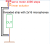
Now I am planning to build this:
1615825701345.png


2x 15 mics spcaced 50.7mm (10holes), I will use the31th channel for a reference mic and the 32th channel for timing/adda convertor reference

The mics will be spaced ca 20cm apart in the strips, the combi of the linear actuator for up/down movement of the whole array and the servo for rotation will make almost any position possible.

the strips with mics wil weight around 1kg, so very easy to position with low force motors

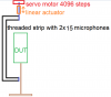
I will mount the mics inside the holes (have to drill the holes bit bigger) and have the strips pointed sideways to the DUT. This way there is only a 2mm wide, 5mm deep strip in the way for the sound to reach the second strip with mics, which is more "invisible" to the soundwaves at 20k than a 1/4 inch mic.
Top view of the strip with the mic in place:
1615826542233.png


I am planning to connect the analog differential mems mics directly to this: https://tascam.com/us/product/ml-32d/top 32channel in-out dante convertor that I alread own, just because dante is very convinient and I dont have to buy anything this way.

I jus came accross this very nice paper, which is highly relevant;
EDIT: link not working, updated link: https://drive.google.com/file/d/1JdUX7GXndH9DFTqxukMX2gebv0prMMQU/view?usp=sharing

One question that maybe amir or someone else who has seen the klippel in action can answer, does the klippel scan the cylinder according to A or B on the picture below? (top view/ DUT seen from above)

1615825375277.png

@NTK; once you find the time to make a a bit more progression with the Matlab ( I am especially lost on the lms coefficient fitting part) I wil start doing simulations in matlab. The quoted articel has a lot of good matlab code examples at the end, I have to look into this to see if it is usable.
though my progress is slow, I am highly enjoying the thought gymnastics in this project :)

regards,
Kees
 

Attachments

  • 1615824629851.png
    1615824629851.png
    52.4 KB · Views: 93
  • 1615824717995.png
    1615824717995.png
    49.4 KB · Views: 87
Last edited:
Top Bottom