Neumann are taking these matters very seriously so they want to do several tests (also with the Klippel NFS) before replying, it just takes some time.
Not saying I don’t believe but what feedback are you aware of and can you share it

Neumann are taking these matters very seriously so they want to do several tests (also with the Klippel NFS) before replying, it just takes some time.
I have good email contact with their chief engineer as I have been at their engineering centre a coupe of times but won't publish it, so you have to believe me or not, anyway the future will show.
") that would be cool.
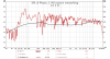
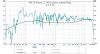
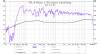
that would be cool.The Genelec 8341a results will be posted tonight (probably late). And I have found the cause of the ripple/comb filtering in treble frequencies and have fixed it in the Genelec measurements. I am still running some experiments in that area.Nope, don't think we've seen anything from them. It would be interesting to see their response on the bass dip, since it seems to be real, albeit minor since it's obliterated by room modes in all real-world situations.
Unclear if the 13khz dip on #2 is an out-of-spec sample or something else, and the 5-10khz "comb filtering" seems to be present in every speaker measured thus far, so it's looking increasingly like a systematic issue.
Will be interesting to see what happens with the Genelec 8341a measurement since that is another allegedly close-to-ruler-flat speaker.
How late (I have a family get together/dinner and would like to know if I should be checking my phone for your posting)?The Genelec 8341a results will be posted tonight (probably late). And I have found the cause of the ripple/comb filtering in treble frequencies and have fixed it in the Genelec measurements. I am still running some experiments in that area.
The Genelec 8341a results will be posted tonight (probably late). And I have found the cause of the ripple/comb filtering in treble frequencies and have fixed it in the Genelec measurements. I am still running some experiments in that area.
Setup RSS to SMS (or Telegram) notifications (using IFTTT or similar)How late (I have a family get together/dinner and would like to know if I should be checking my phone for your posting)?
I can post the measurements this afternoon if we don't need a listening test. I don't want to move the speaker for some other tests I need to run on it.How late (I have a family get together/dinner and would like to know if I should be checking my phone for your posting)?
I can post the measurements this afternoon if we don't need a listening test. I don't want to move the speaker for some other tests I need to run on it.
Otherwise, I will be posting at midnight (pacific time) since we will be going to dinner and have a long drive back.
I can post the measurements this afternoon if we don't need a listening test. I don't want to move the speaker for some other tests I need to run on it.
Otherwise, I will be posting at midnight (pacific time) since we will be going to dinner and have a long drive back.
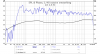
overlays between the two using the "separate" feature of REW. Otherwise they are on top of each other:
View attachment 51314View attachment 51315View attachment 51316View attachment 51317
I tried to find instructions on how to do this, but failed. Maybe you could tell me?Thanks! Were you able to take any gated measurements?
I tried to find instructions on how to do this, but failed. Maybe you could tell me?
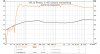
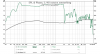
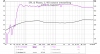
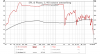
Gated response. I added the impulse window view so that @napilopez can see if I did it right. The window was 0.5, which was the lowest REW would let me set it.
View attachment 51331View attachment 51332View attachment 51333

The measurements are #2 and #3 at 3 ft away from the speaker.Cheers! I assume this was based on the measurements you'd already made? Where was the speaker when you made the measurement?
Unfortunately it seems you have a very early reflection which means the data isn't too useful for gating. Were the speakers on a desk or table, perhaps?
The measurements are #2 and #3 at 3 ft away from the speaker.
I placed it in the middle of the room, on top of some cushions on top of an ottoman. Bottom of the speaker was about 2ft off the ground. The speaker was at the edge of the ottoman.