Have you seen this?
 www.somasonus.net
Box Construction Methods | somasonus
www.somasonus.net
 www.somasonus.net
Yes, I've looked it through once regarding ports. I have not looked through the CLD tests though. I did my CLD cabinets 2005, and at that time I just went with recommendations how to do it from another forum and that was to build the speaker using MDF boards of the same thickness glued together with 1 mm of DG-A2 glue. It was a bit tricky and the glue was really a mess to work with, but at least the results were satisfactory.Have you seen this?
Box Construction Methods | somasonus
Very interesting.I can add a note regarding distortion measurements using microphone measurements, where I found one of my original threads from 2005 in a Swedish forum (time files... now I know how old my speakers are). I measured fixed tones with a microphone and found the following for an older-built enclosure, second and third distortion component.
120 Hz: -48.6 dB (0.37%); -53.2 dB (0.22%)
160 Hz: -51.8 (0.26%); -52.4 (0.24%)
200 Hz: -55.5 (0.17%); -57.9 (0.13%)
250 Hz: -54.3 (0.19%); -63.0 (0.07%)
315 Hz: -54.1 (0.20%); -56.0 (0.16%)
400 Hz: -51.6 (0.26%); -59.4 (0.11%)
500 Hz: -55.3 (0.17%); -38.6 (1.17%)!!!!
630 Hz: -51.7 (0.26%); -58.5 (0.12%)
800 Hz: -56.6 (0.15%); -47.6 (0.42%)
1000 Hz: -51.6 (0.26%); -53.7 (0.21%)
When I built the new constrained layer cabinet I got this:
100 Hz: 0.33%, 0.15%
125 Hz: 0.26%, 0.26%
160 Hz: 0.18%, 0.04%
200 Hz: 0.39%, 0.32%
250 Hz: 0.57%, 1.04%!!!
315 Hz: 0.28%, 0.07%
400 Hz: 0.27%, 0.14%
500 Hz: 0.21%, 0.09%
630 Hz: 0.03%, 0.47%
800 Hz: 0.13%, 0.14%
1000 Hz: 0.13%, 0.39%
So also the acoustic output from the speaker showed distortion components similar to the vibration of the cabinets shown, and shifted from 500 Hz to 250 Hz in the constrained layer cabinet.
Original thread in Swedish:
 www.stereophile.com
To be fair, I have not seen any harmonic distortion results from accelerometer measurements from Stereophile, only the primary frequency as you show above. So I don't know what these say. It is more complicated since an enclosure which is glued together should be "linear". There is something else giving nonlinearities, and the suspicion is the driver to enclosure interface. One solution is to glue the driver to the enclosure, but I do not want to experiment with that. At least not at the moment...Very interesting.
As we can see in your measurements, the constrained layer cabinet has higher distortion from the cabinet at a lower frequency , at 250 Hz.
The cabinet without constrained layer has its highest cabinet resonance and distortion at 500 Hz .
Regarding lowering the resonance frequency of the cabinet :
This is in my opinion not entirely good - in my opinion its better to have more stiff materials like aluminium or birch plywood, putting the cabinett resonances up in frequency where they are less audible and more easy to control. If its done right.
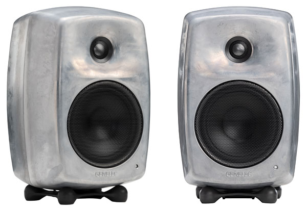
Genelec has made an outstanding cabinet with the loudpeaker G3, the same box as 8030c. The strongest resonance is at 637 Hz from the cabinet. This is a better result than the class leading Kef ls50 Meta.
Genelec G Three active loudspeaker
My review samples of Genelec's G Three powered loudspeaker came with a little hand-sized green and tan cardboard card featuring a poem in bold black letters dated 1898: At the cottage window a little bird sang. And the light of the window did flicker. And look. The roof up it sprang and the...
”I investigated the enclosure's vibrational behavior with a plastic-tape accelerometer. It was extremely inert. The only resonant mode I found was on the sidewall, at 637Hz (fig.1), but this is vanishingly low in level, even at SPLs >90dB.”
View attachment 222835
I think ( without knowing everything ) that vibration attenuation treatment must and can be done in different ways depending on the frequency the loudspeaker will play . One seems not to be helped using constraining layer constructions in subwoofers , where ordinary stiff 2 cm birch plywood without bracing seems to be good enough up to 150 Hz ( 48 dB/ oct crossover and cube formed, 40*40 cm ).To be fair, I have not seen any harmonic distortion results from accelerometer measurements from Stereophile, only the primary frequency as you show above. So I don't know what these say. It is more complicated since an enclosure which is glued together should be "linear". There is something else giving nonlinearities, and the suspicion is the driver to enclosure interface. One solution is to glue the driver to the enclosure, but I do not want to experiment with that. At least not at the moment...
Agree, subwoofer enclosures are not a real problem below 100 Hz, unless there are special cases with non-linearities. With respect to frequency, I think distortion it more audible in the upper voice range than in the lower. So it all depends.I think ( without knowing everything ) that vibration attenuation treatment must and can be done in different ways depending on the frequency the loudspeaker will play . One seems not to be helped using constraining layer constructions in subwoofers , where ordinary stiff 2 cm birch plywood without bracing seems to be good enough up to 150 Hz ( 48 dB/ oct crossover and cube formed, 40*40 cm ).
So, then you have 150-20000 Hz where ( maybe ) a clue to low cabinet vibration comes from B/W Matrix structure , raising all resonanses above 600 Hz making them higher Q resonances and therefore maybe less hearable. Or using very stiff material.
BBC had , in the 1977 report, another interesting approach above 250 Hz - it was using only 10 mm plywood and a soft bitumen material with equal thickness.
Read more here, page 10 :
 www.audiosciencereview.com
www.audiosciencereview.com
www.audiosciencereview.com
Genelec has made an outstanding cabinet with the loudpeaker G3, the same box as 8030c. The strongest resonance is at 637 Hz from the cabinet. This is a better result than the class leading Kef ls50 Meta.
”I investigated the enclosure's vibrational behavior with a plastic-tape accelerometer. It was extremely inert. The only resonant mode I found was on the sidewall, at 637Hz (fig.1), but this is vanishingly low in level, even at SPLs >90dB.”Genelec G Three active loudspeaker
My review samples of Genelec's G Three powered loudspeaker came with a little hand-sized green and tan cardboard card featuring a poem in bold black letters dated 1898: At the cottage window a little bird sang. And the light of the window did flicker. And look. The roof up it sprang and the...
Oh ! Thanks !You can find an article I wrote on measuring cabinet vibrational behavior like this at https://www.stereophile.com/features/806/index.html
John Atkinson
Technical Editor, Stereophile
")
The use of these devices here and in your article leave me wondering why the manufacturers advice on mounting isn't being followed.You can find an article I wrote on measuring cabinet vibrational behavior like this at https://www.stereophile.com/features/806/index.html
John Atkinson
Technical Editor, Stereophile
So conclusion is that hard coupling to the floor (oak mounted on sand in this case) causes more movement in the bass region of the speaker compared to soft feet.
You can look at the initial measurements made the day before and judge for yourself regarding repeatability. Below the harmonic distortion from the two enclosures. (The action-reaction force measurements with soft and hard feet are not comparable between days, as I wrote there were difference in the setup (more stable metal support for the speaker and plugged port).)The use of these devices here and in your article leave me wondering why the manufacturers advice on mounting isn't being followed.
From reading the data sheet of the PVDF sensor, it calls for the device to be mounted by the contact legs. I see this as standing perpendicular to the surface being measured ... allowing the sensor to vibrate freely above in open air ... not taped flat to the surface being measured for vibration.
Here, Thomas_A, you've just double face taped the device you're using to the enclosure walls and left the connector lead free to interact with the sensor. The data sheet for your device requires secure attachment of both the sensor and the the connecting wire lead for a good measurement.
It's nice to see measured effects of enclosure vibration but how accurate is the data being presented?
www.audiosciencereview.com
There was a lengthy discussion about this matter here:it's actualy obvious if you think about it. hard coupling want absorb anything, the soft feet will "mute" the surface like a pad on a snaredrum
www.audiosciencereview.com
Double-sided tape for accelerometers, a note from MSI here:The use of these devices here and in your article leave me wondering why the manufacturers advice on mounting isn't being followed.
From reading the data sheet of the PVDF sensor, it calls for the device, when used as a vibration sensor, to be mounted by the contact legs. I see this as the sensor standing perpendicular to the surface being measured ... allowing the sensor to vibrate freely above in open air ... not taped flat to the surface being measured for vibration.
Here, Thomas_A, you've just double face taped the device you're using to the enclosure walls and left the connector lead free to interact with the sensor. The data sheet for your device requires secure attachment of both the sensor and the the connecting wire lead for a good measurement.
It's nice to see measured effects of enclosure vibration using both these types of sensors but how accurate is the data being presented?
Some constructors ( i.e I.Ö ) says it might be an advantage to use different thickness of MDF in the loudspeaker cabinet. If the baffle are made of 22 mm MDF , then it should be better to make the sides of 16 mm and the back of the speaker 19 mm . This avoids the ”tuning fork effect”.To be fair, I have not seen any harmonic distortion results from accelerometer measurements from Stereophile, only the primary frequency as you show above. So I don't know what these say. It is more complicated since an enclosure which is glued together should be "linear". There is something else giving nonlinearities, and the suspicion is the driver to enclosure interface. One solution is to glue the driver to the enclosure, but I do not want to experiment with that. At least not at the moment...
For the front and rear baffle this could theoretically make sense as you don't want them to have the same eigenfrequencies, although alone due to the frontal driver placements they would be different. For the side ones it would also make sense if the dimensions are identical to the front and rear one (which is rare and should be better avoided also due to internal air volume modes), in the end its better though to just engineer them all sufficiently stiff (for example through brackets) and sufficiently damped (through viscoelasticity).Some constructors ( i.e I.Ö ) says it might be an advantage to use different thickness of MDF in the loudspeaker cabinet. If the baffle are made of 22 mm MDF , then it should be better to make the sides of 16 mm and the back of the speaker 19 mm . This avoids the ”tuning fork effect”.
That's a selective/partial conclusion though as he writes also:Linkwitz seems to come to the conclusion that its better to push the panel vibration modes up in frequency - i.e. by increasing the panel stiffness.
Thus as said several times, high stiffness on its own is not enough, damping is as important.but often goes together with increasing the mechanical Q of resonance. Dampening the panel by using a constrained layer that dissipates energy will reduce Q.