
-
WANTED: Happy members who like to discuss audio and other topics related to our interest. Desire to learn and share knowledge of science required. There are many reviews of audio hardware and expert members to help answer your questions. Click here to have your audio equipment measured for free!
You are using an out of date browser. It may not display this or other websites correctly.
You should upgrade or use an alternative browser.
You should upgrade or use an alternative browser.
Post Directiva r1 Passive Crossovers here
- Thread starter Rick Sykora
- Start date
- Joined
- Sep 16, 2019
- Messages
- 1,193
- Likes
- 2,646
Copy/paste from other thread.
Please let me preface by saying I've never actually built a passive network, and I'm sure I've made mistakes. But after getting to know Vcad a bit I came up with the following results for a passive network. If anyone who has experience with passive networks wants to take a look and correct my work.. by all means have a go.
Update after community feedback


Update after community feedback
Attachments
Last edited:

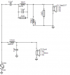
A more minimalist approach:

Approximately 2K LR2. The woofer response isn't ideal with LR2 but it works okay. Waveguide tweeters generally need a wide notch above Fc due to the boost there- if you attenuate them like a normal tweeter, the top octave comes down too much.

Approximately 2K LR2. The woofer response isn't ideal with LR2 but it works okay. Waveguide tweeters generally need a wide notch above Fc due to the boost there- if you attenuate them like a normal tweeter, the top octave comes down too much.
This one is a bit better in my opinion. Due to the good directivity matching between drivers, a higher order crossover can be used while still blending the drivers well. This is basically LR4 at 1800. Getting the woofer to do a higher LR4 roll off is possible but you need more components, and I think the DXT can handle 1800hz fine.


The voltage dividing resistors in the tweeter network are needed to keep HF where you want. Overall tonality can be adjusted with the 1.5 ohm resistor, just changing the ratio will bring the entire tweeter level up or down.
The voltage dividing resistors in the tweeter network are needed to keep HF where you want. Overall tonality can be adjusted with the 1.5 ohm resistor, just changing the ratio will bring the entire tweeter level up or down.
For a more experimental approach, try this eighth order crossover:


Note the hump in the DI is smaller due to the dramatically reduced crossover region, but you have a notch in the reflections.
Note the hump in the DI is smaller due to the dramatically reduced crossover region, but you have a notch in the reflections.
I assumed due to the craziness of the purifi woofer that an active approach would be necessary, but in the properly sized box it is very well behaved. It's actually a breeze to work with by the standards of hifi woofers. The DXT tweeter is a bit more difficult but no harder than any tweeter with a waveguide boost. A passive crossover is totally viable for this speaker in my opinion.
The LR4 crossover could be built with decent components from PE for $150 with free shipping.
The LR4 crossover could be built with decent components from PE for $150 with free shipping.
Do not build this:


The tweeter is first order butterworth at 3k. Accurately hitting a first order slope is really difficult which is why you see four notch filters. Power handling would not be ideal but Richard Vandersteen makes a decent living so maybe he knows something I don't.
Single inductor on the woofer gives as good a shallow roll off as you're going to get with this woofer (or almost any woofer - maybe the Satoris are a bit more extended). Impedance is irresponsibly low due to the low overall resistance provided by the crossover.
Still, it's interesting to see that the DI and reflections are not dramatically different from the other crossovers. That just goes to show how well these drivers match up.
I wasn't interested in the purifi woofer, and I'm still not, but I'm very keen on the purifi midrange (if it is a midrange.) It has the same resonance as the bigger woofer, but at 5K instead of 4K, but it's not that bad a resonance really, and the passband is ultra smooth. Combined with the small diameter and high xmax, you have a very interesting small driver.
I downloaded the files, and I'd like to load them into my own software to play around with them a bit. However, it's unclear to me how the Z offset between the woofer and tweeter is handled. I didn't see anything in the vxp file, nor in the txt files about it. Has it already been addressed in the phase response of the txt files?
OP
- Thread Starter
- #10
I downloaded the files, and I'd like to load them into my own software to play around with them a bit. However, it's unclear to me how the Z offset between the woofer and tweeter is handled. I didn't see anything in the vxp file, nor in the txt files about it. Has it already been addressed in the phase response of the txt files?
Note it in the tweeter comp...
there is a tweeter delay of 52 us (17.9 mm)
maty
Major Contributor
Copy/paste from other thread.
Please let me preface by saying I've never actually built a passive network, and I'm sure I've made mistakes. But after getting to know Vcad a bit I came up with the following results for a passive network. If anyone who has experience with passive networks wants to take a look and correct my work.. by all means have a go.
The vertical lobe can be improved but it would require physically moving the woofer in the Z axis to the front with an extra 3/4" baffle and adjusting the crossover after.
View attachment 158070
View attachment 158071
View attachment 158072
View attachment 158075
View attachment 158073
View attachment 158074
overlay with original (active version)
View attachment 158076
85 dB and minimum at 3,3 Ohms? is not a very good idea.
- Joined
- Sep 16, 2019
- Messages
- 1,193
- Likes
- 2,646
85 dB and minimum at 3,3 Ohms? is not a very good idea.
Any thoughts on how to improve on it? I'm looking to learn.
Thanks for the reply, but I'm still confused. If all excess phase has been eliminated from both measurements, then they are out of alignment with each other, and the amount of misalignment would be angle dependent.
I suspect what you're implying is that the relative phase differences between the tweeter and woofer files is correct (representative of the phase difference that would be measured at the mic position associated with each file) , and that you added a delay to the tweeter in your processing string for time alignment (on axis time alignment).
OP
- Thread Starter
- #14
Thanks for the reply, but I'm still confused. If all excess phase has been eliminated from both measurements, then they are out of alignment with each other, and the amount of misalignment would be angle dependent.
I suspect what you're implying is that the relative phase differences between the tweeter and woofer files is correct (representative of the phase difference that would be measured at the mic position associated with each file) , and that you added a delay to the tweeter in your processing string for time alignment (on axis time alignment).
Sorry that is all I can offer. @ctrl did all that work and so for details, would need to seek his input.
- Joined
- Jan 15, 2020
- Messages
- 6,895
- Likes
- 16,883
The vertical directivity should be quite inferior though which often gets hiddem and ignored in the total DI.Still, it's interesting to see that the DI and reflections are not dramatically different from the other crossovers.
Tim, congratulations on wanting to learn the art of passive crossover design. I've never seen a good tutorial on this subject, but I would be happy to give you some pointers. You might know a lot of this, but it has taken me years to learn what I know. Others at ASR know much more than me but hopefully I can help.Any thoughts on how to improve on it? I'm looking to learn.
The first thing you need to understand is that passive filters are expensive and take up space. As a result, we need to be judicious about what we choose to correct and what we do not. The crossover you created would be really large and difficult to even fit in the box.
If you look at crossovers of even fairly expensive speakers, you will notice they tend to be simple. It's rare to see a bunch of RLC notch filters in a commercial speaker, for example. A passive filter is an economical and convenient thing, but if done correctly, it can achieve very high quality.
Tips:
-First, correct the big things first and then move to smaller stuff. The most important component by far is the first inductor in the woofer circuit. I managed to get a decent LR4 response using one coil and one cap.
-See what the drivers want to do. Work with the existing roll-off of the drivers. Avoid their troubled zones rather than trying to correct them. Generally, a second order roll off is tricky but doable. Fourth order is generally quite easy. Jeff Bagby was the master at this in the DIY sphere. He has many designs where he got immaculate responses out of only a handful of components:
-Our CAD software shows us the response all the way to -50db. Irregularity at this low a level in the stop band of a driver will not impact the final response that much. It's okay for your response to deviate from your target line at this low level. Focus on getting the response correct in the 0 to -20 region.
-Don't over-correct. If you have a particularly egregious resonance, by all means address it, but these drivers are quite smooth and operating in their pistonic comfort zone. Not a lot of resonance or breakup mitigation is needed.
- If you have polar data like this, the phase window isn't that meaningful. It only shows phase in the design axis, and the only reason why getting your drivers to play in phase at the crossover frequency is important is that if they are very much out of phase on axis, they will be very much IN phase at some other point in space, indicating a peak off axis. You will see this in the sonogram chart.
- Imitate other people's crossover filters. As I mentioned, manufacturers' filters are cost constrained and typically do the bare minimum, so skilled DIYers are the place to look. See crossovers by Jeff Bagby, Troels Graveson, Speakerdesignworks and AudioExcite for good examples.
- The basic order for crossover components is, for a woofer, a series coil, then a parallel cap, then another coil and so on to get the slope you need. For a tweeter, it is the same but reversed - series cap, parallel coils. Then you can put notch filters if needed (and many designers use them only sparingly) The first component in that sequence is the most impactful. I like to add resistors to bring down tweeter level after all the main components. Experiment with using one series resistor or using a voltage divider like I did in my LR4 design. Midrange drivers are much trickier to design filters for since they have a lot of components which interact, and tend to be expensive as well, requiring big capacitors. Avoid designing a passive 3 way as a first project.
- If your woofer has a hump in the response and you want to bring down a large region, you can turn the first coil into a sort of notch. See my LR2 design - the first coil has a resistor and cap below it. This brings some notch-like behavior to what is the primary low pass coil.
- Passive crossovers should be elegant. It is very easy for a pair of passive crossovers to have so many components that they exceed the cost of a minidsp. If you get to that point, the passive crossover starts to make less sense. Don't be afraid to turn on 1/3 octave smoothing sometimes to see if the overall trend of your speaker is correct - small blips can obscure the big picture.
- Impedance is a complicated subject, but low impedance issues are caused by the fact that at any given frequency, the impedance is the result of the combination of your tweeter and woofer impedance. Maybe that's obvious, but let's break that down.
The purifi woofer has an impedance which dips down to 4 ohms between 200 and say 400 hz by itself. The impedance of the naked tweeter at 200hz is 6.2 ohms. To calculate the total impedance of the un-filtered drivers playing together, just add them like you would add resistors in parallel (hence the name parallel crossover):
1/R(Total) = 1/R1 + 1/R2 + 1/R3
If you do the math, you get around 2.4 ohms, which is very low and potentially problematic.
How do you rectify this? Well, the way we make things quieter is by adding resistance to them. If you look at the impedance of a single woofer with a coil on it, the coil adds resistance as frequency increases. This makes the woofer quieter as frequency goes up. The cap does the same thing in reverse for the tweeter.
If you want to keep your impedance above four ohms, you need to make sure your crossover filters are attenuating (adding resistance) sufficiently at the frequencies where the driver's impedance is naturally low. In the case of this woofer, you need to make sure the tweeter filter has a ton of resistance at 200hz, because the woofer is already at 4 ohms there. In your case, the reason you are down to 3.5 ohms is because at 200hz, your tweeter filter impedance is 28 ohms. You need to add some attenuation to the tweeter in that region. Simply using a more conventional crossover topology like the first two I show will probably get that done. Start by adding a coil in parallel after that first cap. Then worry about notches and bringing the overall level down. That first cap and coil will guarantee that after a certain point, the tweeter impedance is dropping like a rock as frequency goes down.
Other crossover tools show the impedance of your drivers separately and then the total, but VCAD doesn't do this for some reason. It can make rectification of impedance issues much easier.
- Joined
- Sep 16, 2019
- Messages
- 1,193
- Likes
- 2,646
Tim, congratulations on wanting to learn the art of passive crossover design. I've never seen a good tutorial on this subject, but I would be happy to give you some pointers. You might know a lot of this, but it has taken me years to learn what I know. Others at ASR know much more than me but hopefully I can help.
The first thing you need to understand is that passive filters are expensive and take up space. As a result, we need to be judicious about what we choose to correct and what we do not. The crossover you created would be really large and difficult to even fit in the box.
If you look at crossovers of even fairly expensive speakers, you will notice they tend to be simple. It's rare to see a bunch of RLC notch filters in a commercial speaker, for example. A passive filter is an economical and convenient thing, but if done correctly, it can achieve very high quality.
Tips:
-First, correct the big things first and then move to smaller stuff. The most important component by far is the first inductor in the woofer circuit. I managed to get a decent LR4 response using one coil and one cap.
-See what the drivers want to do. Work with the existing roll-off of the drivers. Avoid their troubled zones rather than trying to correct them. Generally, a second order roll off is tricky but doable. Fourth order is generally quite easy. Jeff Bagby was the master at this in the DIY sphere. He has many designs where he got immaculate responses out of only a handful of components:

-Our CAD software shows us the response all the way to -50db. Irregularity at this low a level in the stop band of a driver will not impact the final response that much. It's okay for your response to deviate from your target line at this low level. Focus on getting the response correct in the 0 to -20 region.
-Don't over-correct. If you have a particularly egregious resonance, by all means address it, but these drivers are quite smooth and operating in their pistonic comfort zone. Not a lot of resonance or breakup mitigation is needed.
- If you have polar data like this, the phase window isn't that meaningful. It only shows phase in the design axis, and the only reason why getting your drivers to play in phase at the crossover frequency is important is that if they are very much out of phase on axis, they will be very much IN phase at some other point in space, indicating a peak off axis. You will see this in the sonogram chart.
- Imitate other people's crossover filters. As I mentioned, manufacturers' filters are cost constrained and typically do the bare minimum, so skilled DIYers are the place to look. See crossovers by Jeff Bagby, Troels Graveson, Speakerdesignworks and AudioExcite for good examples.
- The basic order for crossover components is, for a woofer, a series coil, then a parallel cap, then another coil and so on to get the slope you need. For a tweeter, it is the same but reversed - series cap, parallel coils. Then you can put notch filters if needed (and many designers use them only sparingly) The first component in that sequence is the most impactful. I like to add resistors to bring down tweeter level after all the main components. Experiment with using one series resistor or using a voltage divider like I did in my LR4 design. Midrange drivers are much trickier to design filters for since they have a lot of components which interact, and tend to be expensive as well, requiring big capacitors. Avoid designing a passive 3 way as a first project.
- If your woofer has a hump in the response and you want to bring down a large region, you can turn the first coil into a sort of notch. See my LR2 design - the first coil has a resistor and cap below it. This brings some notch-like behavior to what is the primary low pass coil.
- Passive crossovers should be elegant. It is very easy for a pair of passive crossovers to have so many components that they exceed the cost of a minidsp. If you get to that point, the passive crossover starts to make less sense. Don't be afraid to turn on 1/3 octave smoothing sometimes to see if the overall trend of your speaker is correct - small blips can obscure the big picture.
- Impedance is a complicated subject, but low impedance issues are caused by the fact that at any given frequency, the impedance is the result of the combination of your tweeter and woofer impedance. Maybe that's obvious, but let's break that down.
The purifi woofer has an impedance which dips down to 4 ohms between 200 and say 400 hz by itself. The impedance of the naked tweeter at 200hz is 6.2 ohms. To calculate the total impedance of the un-filtered drivers playing together, just add them like you would add resistors in parallel (hence the name parallel crossover):
1/R(Total) = 1/R1 + 1/R2 + 1/R3
If you do the math, you get around 2.4 ohms, which is very low and potentially problematic.
How do you rectify this? Well, the way we make things quieter is by adding resistance to them. If you look at the impedance of a single woofer with a coil on it, the coil adds resistance as frequency increases. This makes the woofer quieter as frequency goes up. The cap does the same thing in reverse for the tweeter.
If you want to keep your impedance above four ohms, you need to make sure your crossover filters are attenuating (adding resistance) sufficiently at the frequencies where the driver's impedance is naturally low. In the case of this woofer, you need to make sure the tweeter filter has a ton of resistance at 200hz, because the woofer is already at 4 ohms there. In your case, the reason you are down to 3.5 ohms is because at 200hz, your tweeter filter impedance is 28 ohms. You need to add some attenuation to the tweeter in that region. Simply using a more conventional crossover topology like the first two I show will probably get that done. Start by adding a coil in parallel after that first cap. Then worry about notches and bringing the overall level down. That first cap and coil will guarantee that after a certain point, the tweeter impedance is dropping like a rock as frequency goes down.
Other crossover tools show the impedance of your drivers separately and then the total, but VCAD doesn't do this for some reason. It can make rectification of impedance issues much easier.
Thank you for this thorough explanation! Much appreciated! I'll see if I can put it to good use.
")
This looks very promising.I was able to simplify everything and keep the impedance from dipping under 4 ohm.
As long as the loudspeaker can still be called a 4 Ohm LS according to the official designation (impedance always >= 3.2 Ohm), I don't see any problem if the impedance falls below 4 Ohm.
But your min 4 ohms are of course even better.
Make sure that the component values always remain within the E12 series range. A coil with 2.31mH will be hard to find
I agree that the result looks good in terms of frequency response, directivity, impedance, and parts count. I wouldn't concern myself with the 2.31 mH inductor nearly as much as the 15 mH inductor in the tweeter circuit. That would be... atypical (and expensive).This looks very promising.
...
Make sure that the component values always remain within the E12 series range. A coil with 2.31mH will be hard to find
Similar threads
- Replies
- 49
- Views
- 6K