
-
WANTED: Happy members who like to discuss audio and other topics related to our interest. Desire to learn and share knowledge of science required. There are many reviews of audio hardware and expert members to help answer your questions. Click here to have your audio equipment measured for free!
You are using an out of date browser. It may not display this or other websites correctly.
You should upgrade or use an alternative browser.
You should upgrade or use an alternative browser.
Measurements of speaker cables in frequency and time domain
- Thread starter pma
- Start date
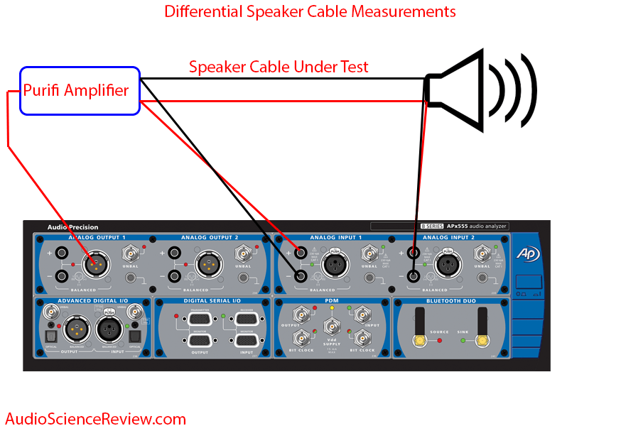
What are you talking about? For the third time, I made the same measurement you made, with a real amp at the source and real speaker as the sink:I did not use a digital scope for measurements of FR of the real cables loaded with real speakers, sorry. My measurements of speaker cables are at least as good as yours and on contrary they show real life situations. Measurements of a speaker cable FR loaded with 200k input impedance of the AP is useless. Same applies to attempts to measure “cable distortion”.
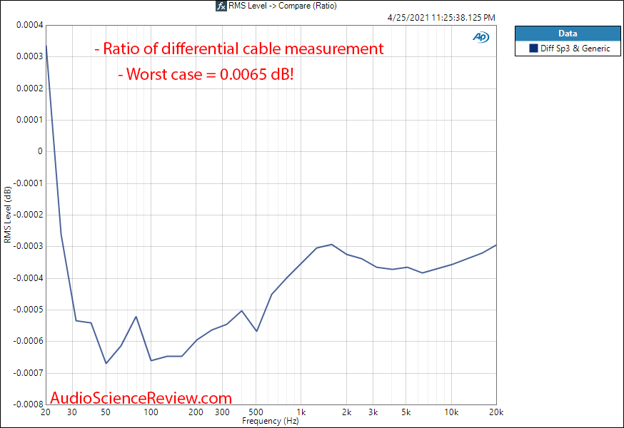
I showed not only this measurement, but tiny, 0.006 dB difference between two cables:
Your scope lacks the resolution and accuracy to show the above measurement. Yes, it can spit out numbers but there is no reliability in them.
Reflections on a speaker cable? Are you for real?And yes, if we need to measure cable reflections, the AP is close to useless and the digital scope with rise time in ns is a perfect tool. This is a different story and different tools are needed than in case of audio band frequency response.
Sure, but what product from a large company tests badly these days?
??? Data are there for you to make your decision. What's more do you need/want?
- Thread Starter
- #84
OK, by now we were talking mostly about the frequency response effect of the speaker cable driven from power amplifier and loaded with a real speaker. We were measuring the frequency response by means of REW software and a soundcard with a balanced input, in 24-bit resolution, at the amplifier output before the cable (point B) and at the speaker terminals behind the cable (point A). Then we made A/B plot (in REW software) to show the cable effect in isolation. We also have seen some square wave responses, measured by a digital oscilloscope.
Cable reflections were mentioned only briefly. There is an excellent application note AN-991 by Texas Instruments:
https://www.ti.com/lit/an/snla043/snla043.pdf
that explains the cable reflections and shows many oscilloscope measurements of reflections due to load impedance mismatch. Yes audio frequencies cannot create such reflections in a speaker cable, but EMI induced high frequency signals or spikes due to SMPS or digital circuits action may initiate such reflections.
An example of measurements with our 5m speaker cable zipcord follows.

This is a 5m zipcord cable driven from 50 ohm source (impulse generator with rise time <10ns) and unloaded (open) at the end of the cable. Please compare with measurements in TI app note that show impedance mismatch.
The same cable, now terminated by 50 ohm resistor and driven from 50 ohm source.

The impedance mismatch is still here, because the zipcord characteristic impedance is higher than 50 ohm. However, the overvoltage resulting from the open end reflection has gone. Please also note that the steady-state voltage swing is halved because of 50ohm/50ohm divider ratio.
Both measurements were done at the end of the speaker cable.
Cable reflections were mentioned only briefly. There is an excellent application note AN-991 by Texas Instruments:
https://www.ti.com/lit/an/snla043/snla043.pdf
that explains the cable reflections and shows many oscilloscope measurements of reflections due to load impedance mismatch. Yes audio frequencies cannot create such reflections in a speaker cable, but EMI induced high frequency signals or spikes due to SMPS or digital circuits action may initiate such reflections.
An example of measurements with our 5m speaker cable zipcord follows.
This is a 5m zipcord cable driven from 50 ohm source (impulse generator with rise time <10ns) and unloaded (open) at the end of the cable. Please compare with measurements in TI app note that show impedance mismatch.
The same cable, now terminated by 50 ohm resistor and driven from 50 ohm source.
The impedance mismatch is still here, because the zipcord characteristic impedance is higher than 50 ohm. However, the overvoltage resulting from the open end reflection has gone. Please also note that the steady-state voltage swing is halved because of 50ohm/50ohm divider ratio.
Both measurements were done at the end of the speaker cable.
Last edited:
Who said you should use any old cable and you are good to go? I wrote an entire article on differences between 12 gauge wires showing that they are different. It starts with this: https://www.audiosciencereview.com/forum/index.php?threads/when-12-gauge-wire-is-not-12-gauge.3/Exactly. And when folks obsess over differences in -115dB vs. -120dB SINAD on DACS and dismiss the fact that speaker cables can introduce +/- 0.5dB deviations across the audio spectrum, it seems rather inconsistent to me.
Introduction
Why test 12 gauge (AWG) wire? 12 AWG speaker wire is a “safe bet” from performance point of view because anything thinner may interact with the low impedance of your speakers and cause the frequency response to vary beyond threshold of hearing (-0.5 dB). That change can “color” the sound.
Whether the difference is audible or not is not just dependent on the variation but how broad it is. That requires knowing the impedance graph of the speaker. But per above, once you get to proper 12 gauge wire, such differences become moot.
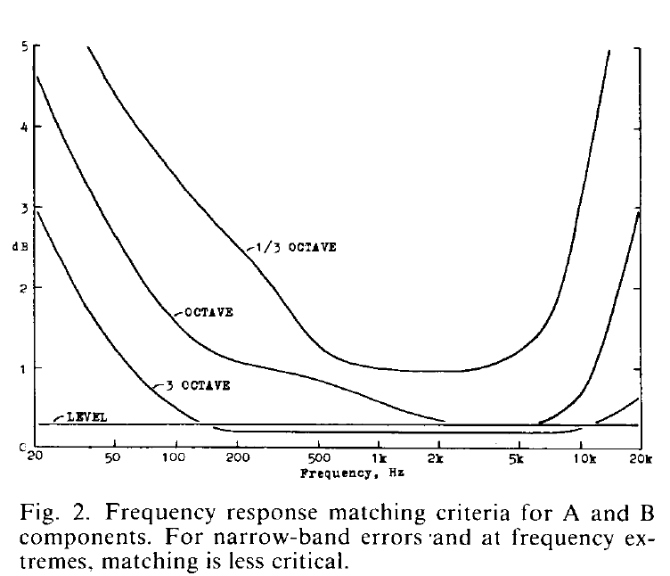
As to bit of roll off at the top end, your speaker is not ruler flat anyway, nor is your audibility great so it is not something that merits attention. If you want to know the threshold of detection, Clark has done some coarse work there and came up with this: "High-Resolution Subjective Testing Using a Double-Blind Comparator:"
As you see, highest sensitivity is in 1 to 5 kHz, not at either extreme.
Oh yeh? You have proof of these reflections a) being there in real audio systems and b) being audible?that explains the cable reflections and shows many oscilloscope measurements of reflections due to load impedance mismatch. Yes audio frequencies cannot create such reflections in a speaker cable, but EMI induced high frequency signals or spikes due to SMPS or digital circuits action may initiate such reflections.
10 ns rise time translates to 35 Mhz bandwidth. Not Kilohertz, but Megahertz. Of course a speaker cable is not designed for use in RF frequencies. You can show all kinds of differences at such wide bandwidths. None has any usability or application to audio.This is a 5m zipcord cable driven from 50 ohm source (impulse generator with rise time <10ns) and unloaded (open) at the end of the cable. Please compare with measurements in TI app note that show impedance mismatch.
You never want to impedance match a speaker to an amp. So the whole topic is out of line.
One note about SINAD. Achieving the highest SINAD ratings relies almost completely on noise level as distortion is usually far lower (by then). Noise can absolutely become audible in a system. It is not subject to masking because it can exist by itself without anything playing. Sensitive IEMs provide incredible magnification of system noise level. This is why I run the 50 mv test for headphone amps. The best we have seen is 94 dB, not 120 dB. Once that drops to 80s, noise becomes audible.
For this reason, it did make sense to also test speaker cables using "SINAD" because it would show noise susceptibility as well.
For this reason, it did make sense to also test speaker cables using "SINAD" because it would show noise susceptibility as well.
One more note: if you are going to test high frequency effects, you better fully control the layout of the cable. Even in my impedance tests, I came up with a fixture to lay every cable identically:

You can't just throw a long cable on the floor and measure it. You will get all kinds of variations. Even how you terminate and pressure that is put on the end terminals matters. Specialized clamping fixtures are used by top brand cable manufactures to make such measurements. Toy setups may not apply I am afraid especially if you are measuring with very wide bandwidth where you can pick up interference from air (e.g. AM radios).
You can't just throw a long cable on the floor and measure it. You will get all kinds of variations. Even how you terminate and pressure that is put on the end terminals matters. Specialized clamping fixtures are used by top brand cable manufactures to make such measurements. Toy setups may not apply I am afraid especially if you are measuring with very wide bandwidth where you can pick up interference from air (e.g. AM radios).
BluesDaddy
Senior Member
- Joined
- Mar 21, 2019
- Messages
- 342
- Likes
- 497
Exactly. And when folks obsess over differences in -115dB vs. -120dB SINAD on DACS and dismiss the fact that speaker cables can introduce +/- 0.5dB deviations across the audio spectrum, it seems rather inconsistent to me.
I'll be the first to admit I don't read everything here, or even a fraction, and certainly not of all the amp reviews for which I'm not in the market, but I can't say I've read comments "obsessing" over SINAD in the way you illustrate.
Yes and I'd like to add two things:
1) The type of people who have the background to understand that +/- 0.5dB is unlikely to be audible are also the same people who are unlikely to be scammed by the "large audible differences" myth.
2) There IS evidence that longer stretches of cables that are not unheard of (20ft, 30 ft) in a domestic setting, particularly when coupled with relatively smaller gauge cable (i.e. 16GA), and particularly if using exotic geometrics that do not prioritize low inductance, CAN result in FR deviations that most people here would agree are audible (i.e. 1-2dB or more over wide frequency ranges).
Regarding 1, you're undoubtedly correct but I suspect there are those who will simply latch on to "measurable difference" and react as I indicated earlier. Regarding 2, I will observe this was a pretty commonly known "don't" when I was getting into hi-fi in the early 70s all the way until I quit really paying attention. The longer the run for a given power output, the larger the gauge of wire needed. I knew people using 18ga or even 24ga that came with those cheap portable systems or that they bought for next to nothing at Radio Shack to wire up their speakers on the other sides of their bedrooms from where their equipment was housed. It sounded "fine" to them. ;-)
Who said you should use any old cable and you are good to go? I wrote an entire article on differences between 12 gauge wires showing that they are different. It starts with this: https://www.audiosciencereview.com/forum/index.php?threads/when-12-gauge-wire-is-not-12-gauge.3/
Hi Amir. Yes, there are definitely differences in LCR parameters across 12 GA speaker cables, as your article demonstrates. I'm not sure who is disagreeing with that.
Whether the difference is audible or not is not just dependent on the variation but how broad it is. That requires knowing the impedance graph of the speaker. But per above, once you get to proper 12 gauge wire, such differences become moot.
As to bit of roll off at the top end, your speaker is not ruler flat anyway, nor is your audibility great so it is not something that merits attention. If you want to know the threshold of detection, Clark has done some coarse work there and came up with this: "High-Resolution Subjective Testing Using a Double-Blind Comparator:"
As you see, highest sensitivity is in 1 to 5 kHz, not at either extreme.
This is good info, I hadn't seen this. Interestingly, I did run across some FR simulations for a simulated loudspeaker load driven by a 12 GA "zip cord" at ~13 ft (4m) length) here.
They are reporting 0.5dB or so peaks or valleys with >4 octave bandwidth based on LCR calcs.
According to your chart above, this would be "potentially" audible.
Attachments
...
I like @pma's detailed technical knowledge, but would have liked him to present his facts in a less "sensationalistic" manner.
The first few posts set up a bit of a straw man argument, namely that "It is impossible to say that cables make no difference". Nobody claims that "cables make no difference" at all.
My sentiments are similar but stronger. I do not like what he did or the way he went about it. He still hasn't explained his criteria for measuring cables, or what problem he perceived in the way Amir did it. He was adamant that it needs to be done not by measuring the voltage at the speaker but rather by measuring the voltage drop end-to-end across the cable. Even though he was adamant about this, he has not explained it. It suggests a belief that the end-to-end voltage drop across the cable reveals the effect of the cable per se, such that if you want to know the effect of the cable per se, this is the measurement you have to take. This makes every bit as much sense as it would make to think that speaker voltage is a property of the speaker per se, i.e., that speaker voltage isn’t affected by the impedance of the cable. Moreover, those two voltages are the voltages associated with impedances in series, and as such their sum has to be equal to the amplifier output voltage less the voltage held back by the amplifier. If he had realized this, would he have been adamant that the voltage needs to be measured across the cable and not at the speaker terminals? I have no tolerance for a person who makes no sincere effort to explain why they are adamant about things about which they are adamant, and that when asked to explain, they say in a very matter-of-fact way that they have explained it. I can't stand this kind of arrogance. Arrrgh.
What are you talking about? For the third time, I made the same measurement you made, with a real amp at the source and real speaker as the sink:
I showed not only this measurement, but tiny, 0.006 dB difference between two cables:
Your scope lacks the resolution and accuracy to show the above measurement. Yes, it can spit out numbers but there is no reliability in them.
Reflections on a speaker cable? Are you for real?
He isn't for real. This is evident on multiple counts. He's never even explained why he was adamant that the measurement needs to be taken across the ends of the cable rather than at the speaker.
... the frequency response effect of the speaker cable driven from power amplifier and loaded with a real speaker. We were measuring the frequency response by means of REW software and a soundcard with a balanced input, in 24-bit resolution, at the amplifier output before the cable (point B) and at the speaker terminals behind the cable (point A). Then we made A/B plot (in REW software) to show the cable effect in isolation.
Again, I'm not able to follow you, and I'm fairly confident that the reason is that you simply aren't coherent. What exactly do you mean by "the effect of the cable in isolation"? When and how did you measure "the effect of the cable in isolation"?
0.5 dB is definitely audible. Just simulate this in EQ and switch on and off.Hi Amir. Yes, there are definitely differences in LCR parameters across 12 GA speaker cables, as your article demonstrates. I'm not sure who is disagreeing with that.
This is good info, I hadn't seen this. Interestingly, I did run across some FR simulations for a simulated loudspeaker load driven by a 12 GA "zip cord" at ~13 ft (4m) length) here.
They are reporting 0.5dB or so peaks or valleys with >4 octave bandwidth based on LCR calcs.
According to your chart above, this would be "potentially" audible.
View attachment 127532
One thing that puzzles me about all this is why it is believed important to focus on the end-to-end voltage for the cable rather than the voltage at the speaker. This suggests the belief that the end-to-end voltage drop across the cable reveals the effect of the cable per se. This makes no more sense than it would make to think that voltage across the speaker is a property of the speaker per se, i.e., that speaker voltage isn’t affected by the impedance of the cable.
The voltage at the speaker is the voltage that ultimately matters. This is obvious, and it is equally obvious that the sum of these two voltages does not vary except for accommodating variation in the voltage held back by the amplifier. As such, how could it matter which of these two voltages you focus on? The only reason that I can think of, for why it might genuinely matter, would be if one of them were immune to the effect of the amplifier output impedance. Neither of the two voltages is immune to the effect of the amplifier output impedance.
What we have here is a simple example of three impedances in series: the output impedance of the amplifier (Ia), the impedance of the cable (Ic), and the impedance of the speaker (Is). The voltage at the speaker:
speaker_voltage = true_output_voltage x Is / (Is + Ic + Ia)
true_output_voltage is what the amplifier output voltage would be across any load if the amplifier had zero output impedance. The cable's end-to-end voltage drop:
voltage_differential_across_cable = true_output_voltage x Ic / (Is + Ic + Ia)
What is the rationale for the strongly held belief that if you want to understand the effect of the cable’s impedance on the voltage across the speaker, you measure voltage across the cable? pma apparently believes that you need to do this because when you do it this way, you somehow measure the effect of the cable "in isolation". Why hasn't anyone challenged this?
Since the conspicuous difference between these two voltages is the difference in order of magnitude, chances are good that the true reason for the strongly held belief is a misinterpretation of some effect of the very large difference in magnitude. There was likely some consequence of this difference in magnitude, that affected the numbers in a way that didn't match expectations, and that was reconciled by wrongly concluding that it is necessary to measure the voltage across the cable and not the voltage across the speaker. Small variations in voltage appear much more significant when viewed relative to the small end-to-end cable voltage vs. the much greater speaker voltage. You need only glance at the two equations above to see that no matter how small Ic happens to be, a given proportional increase in Ic will produce a matching proportional increase in the end-to-end cable voltage even if the increase in Ic is much too small to have any appreciable effect at all on speaker voltage.
To illustrate this point, let us suppose that at some given frequency that the speaker impedance is 100 times greater than the cable impedance and that the speaker voltage is therefore 100 times greater than the end-to-end voltage drop across the cable. Let us suppose that the speaker voltage is 2 volt and that the voltage across the cable is .02 volt. Let us suppose that at some other frequency, the cable impedance is greater by 10%. The voltage drop across the cable will increase by approximately this same percentage. The voltage drop across the cable will increase by .8 dB, and the actual voltage increase will be .002 volt. Assuming no change in the voltage held back by the amplifier, speaker voltage will decrease by .002 volt, from 2 volt to 1.998 volt. The change at the speaker is -.009 dB.
One thing that puzzles me about all this is why it is believed important to focus on the end-to-end voltage for the cable rather than the voltage at the speaker. This suggests the belief that the end-to-end voltage drop across the cable reveals the effect of the cable per se. This makes no more sense than it would make to think that voltage across the speaker is a property of the speaker per se, i.e., that speaker voltage isn’t affected by the impedance of the cable.
The voltage at the speaker is the voltage that ultimately matters. This is obvious, and it is equally obvious that the sum of these two voltages does not vary except for accommodating variation in the voltage held back by the amplifier.
That's exactly how I see it. So, in order to measure the "effect" of a loudspeaker cable on FR, the FR measurement should be taken at the speaker terminals ONLY, and under two conditions: a) WITH a speaker cable wired between the amp and the speaker and b) NO speaker cable wired between the amp and the speaker (in other words, the amp is wired directly to the speaker with extremely short bus bars, or equivalent). An alternative approach would be to take FR measurements at the speaker terminals with various speaker cables inserted in order to compare FR curves. I'm not clear why we would need/want to take a FR measurement at the amplifier terminals in order to answer the question of what effect does speaker cable have on FR under real life conditions.
- Thread Starter
- #97
To understand why a long cable may make an amplifier unstable, let's make the cable simulation.
First, we have a cable test circuit. The cable is driven from 0.001 ohm source and is terminated by 1Mohm resistor in parallel with 100pF capacitor. We measure voltage at 1Mohm terminating resistor.

Let's check the frequency response

This is the voltage transfer, v(out) / v(in). We can see 1st resonant peak at about 4.5MHz followed with decayed peaks, due to 1M//100pF termination.
Time domain

This plot shows what happens if the cable is driven by the 4.5MHz sine wave with 10mV amplitude. It is amplified by cable reflections to 2.5V! Now we can play with source and terminating resistors to see the effects.

We changed the terminating resistor to 50 ohm and oscillations have disappeared.

The same cable sourced from 0.001ohm and terminated by 50ohm.
The plots above explain why sometimes a long speaker cable is an amplifier killer. A terminating resistor prevents such issue.
First, we have a cable test circuit. The cable is driven from 0.001 ohm source and is terminated by 1Mohm resistor in parallel with 100pF capacitor. We measure voltage at 1Mohm terminating resistor.
Let's check the frequency response
This is the voltage transfer, v(out) / v(in). We can see 1st resonant peak at about 4.5MHz followed with decayed peaks, due to 1M//100pF termination.
Time domain
This plot shows what happens if the cable is driven by the 4.5MHz sine wave with 10mV amplitude. It is amplified by cable reflections to 2.5V! Now we can play with source and terminating resistors to see the effects.
We changed the terminating resistor to 50 ohm and oscillations have disappeared.
The same cable sourced from 0.001ohm and terminated by 50ohm.
The plots above explain why sometimes a long speaker cable is an amplifier killer. A terminating resistor prevents such issue.
- Thread Starter
- #98
That's exactly how I see it. So, in order to measure the "effect" of a loudspeaker cable on FR, the FR measurement should be taken at the speaker terminals ONLY, and under two conditions: a) WITH a speaker cable wired between the amp and the speaker and b) NO speaker cable wired between the amp and the speaker (in other words, the amp is wired directly to the speaker with extremely short bus bars, or equivalent). An alternative approach would be to take FR measurements at the speaker terminals with various speaker cables inserted in order to compare FR curves. I'm not clear why we would need/want to take a FR measurement at the amplifier terminals in order to answer the question of what effect does speaker cable have on FR under real life conditions.
I have hoped this was clear, absolutely clear. The cable impedance makes a frequency dependent voltage divider with speaker impedance. The amplifier has finite output impedance which modulates the FR. To eliminate amplifier effect, voltage is measured at amplifier output B and speaker input A and the ratio A/B shows the frequency response added by the cable. The Thevenin theorem. I will show the simulation, cannot explain it better.
R10 = 0.05 ohm is an amplifier output impedance.
Green line is the cable effect
Red (and masked blue) line is the FR at speaker input with ideal cable with zero resistance and inductance and capacitance. V(out) = V(in). That means the FR modulation is a result of the amplifier output resistance R10 = 0.05 ohm.
The green line is now the ideal cable effect = nothing. However, the ideal cable does not exist.
I cannot explain it better and if this is not understand, I can't help. I have to add that I really do not like the philosophical debates about engineering issues.
KSTR
Major Contributor
KSTR
Major Contributor
This is very equivalent to measuring the voltage drop accross the cable. Assuming symmetrically constructed cable, one side will do. The side grounded at the amp would apply and then this can be trivially be measured with a soundcard, may not even need balanced input.That's exactly how I see it. So, in order to measure the "effect" of a loudspeaker cable on FR, the FR measurement should be taken at the speaker terminals ONLY, and under two conditions: a) WITH a speaker cable wired between the amp and the speaker and b) NO speaker cable wired between the amp and the speaker (in other words, the amp is wired directly to the speaker with extremely short bus bars, or equivalent).
Cable has resistance, speaker doesn't draw constant current vs. frequency --> voltage loss along the cable isn't constant, speaker's FR will change. Ohms Law, as simple as that.
Additionally, the speaker's current draw will be non-linear, creating equally distorted voltage drop along the cable. This is also the reason one simply cannot measure distortion of an amp with a real speaker attached (or a load emulation that is nonlinear) and the higher the amp's output impedance the higher the error will be. In practise, it doesn't matter anyway, though. The measured distortion from the speaker output is not affected by a small additional component from the cable (+ amp output impedance).
Similar threads
- Replies
- 133
- Views
- 9K
- Poll
- Replies
- 187
- Views
- 36K
- Poll
- Replies
- 180
- Views
- 25K
- Replies
- 13
- Views
- 783
- Replies
- 30
- Views
- 2K