Mine is quite long!
Don't boast.

Mine is quite long!
With respect I feel you're misunderstanding the point of measurements here... to further your journey, would it not be best to start with the best measuring cables or devices first and then proceed to listening tests of the various well measured components? Would you put this cable in your system knowing it is this bad? Me thinks you're coming across as rather disingenuous here." ...considers audio to be defined exclusively by oscilloscope leads...and noise."
Pretty much sums up my thinking about this site. While many measurements can tell you some general and some specific ideas about the sound of a component, I'm still waiting for the graph that shows how that one particular voice in the background of a song sounds just a bit more realistic with one component and not another. The intricacies and depth of detail that we can hear is so underestimated here.
Says the men who thinks high flexibility is extremely important.Don't boast.
")

Thats fun. I zoomed in and your quite right. Brains who'd trust em?

And that's why chroma subsampling works.
That's true but to the individual, the sound of the cable to him/her came off as "oh just so sublime" and nobody can say otherwise. In this case, his/her brain overcompensate the "idea of improvements" in such a way to make him/her perceive the sound as being better.Thats fun. I zoomed in and your quite right. Brains who'd trust em?
Nice amphenol connectors on that cable for that price.
Don’t think we talking about the same thing.
Pleases allow me to make an crude practical Example
just measured measured 200µA AC RMS from 5V USB power supply to mains ground
And random RCA to 3,5mm cable measured with 27Ohms!
It was tested with a ~"600ohm" DI box and also shorted in both cases its its audible.
My line level 1:1 audio transformers have about 150ohm at DC. that is on both sides so ac impedance is in the order of >300Ohm.
I don't see how 50ohm seems reasonable in this case since Safty Earth ground is mandatory low impedance.
More then the 2000$ cable (i hopeHow many people will be using that cable ?
)Exactly what i'm saying a view hundred ohmes are not unusually high with audiofool gear. but significantly more then the test condition?That's not unusually high is it ? a few kohm is.
https://de.wikipedia.org/wiki/Erdschleife#/media/Datei:Erdschleife_Sender_Empfänger.svgSafety ground resistance has absolutely nothing to do with ground loop currents.

Since its resistance is very low, often less than 1 ohm, the induced currents can be large.
Or Voltage is present caused by induction.Of course when one is using 2 very different outlets over a large distance where both outlets are heavily loaded
I don't think they are legal for consumer electronics in Germany? but i don't know.That's where groundloop breakers are for
Not so common in home systems.

The professional that uses a ****** 10m long questionable cable in this situation doesn't fully understand what he is working with.
Can you link me to what exact test/standard your referring to?And the resistance range I mentioned is not fictional but is used in EMC testing etc
What kind of leakage are you talking about?A groundloop usually is caused by leakage currents from power supplies and lack of proper grounding
Well i don't know how and why you think that's true. Where is the inductance to explain this 100Hz drop of coming from?Besides safety ground may well be a very low for DC to 100Hz
If we are talking about RF start thinking in wavelength! 1/4 lambda of a view Mhz is right in the ballpark of a typical ground loop size...It is very high resistance for RF. It does literally nothing against HF noise.
You saw the picture?
Its clearly a loop and its flowing trough ground? how is and why is that not a ground loop in your mind?
https://en.wikipedia.org/wiki/Ground_loop_(electricity)#Sources_of_ground_current
Exactly what i'm saying a view hundred ohmes are not unusually high with audiofool gear. but significantly more then the test condition?
I can almost see a view kohm, for example from a passive preamp (poti) to the amp.
Or as in my example a TV is maybe ground referenced over the CableTV cable and/or satellite receiver over Antenna ground.
Those grounds are also referenced to Safety/earth ground but someware not locally.
I don't think they are legal for consumer electronics in Germany? but i don't know.
This seems like a common setup for many people i talk to.
And having Noise/Humm issues is a common problem that comes with it.
Well i don't know how and why you think that's true. Where is the inductance to explain this 100Hz drop of coming from?
What kind of leakage are you talking about?
I assume "parasitic interwinding capacitance" this can leak switching frequency currents
and the class y capacitor (pressent to supress switching frequency currents ) leaks mains frequency current
I'm pointing out that this dose not translate to:
" under all conditions its proven that there can't be any cable influence "
" Less professional or less high end gear means the cable can have even less of an influence"
" if the 30$ cable is fine for amir the 50cent cable is fine for me"
Mono is quite fashionable these days amongst the horn/DHT set.
In any case, if it were me and I was using single ended phono (mine runs balanced) and wanted to keep the price rock-bottom, I'd go with something like this. Foamed polyolefin dielectric will give almost no triboelectric effect, low capacitance, and high flexibility (extremely important).
Yes. This Difference in potential can be created by Induction.difference in ground POTENTIAL. When the ground potential is0 you have a loop but it is not an issue.
Any time-varying magnetic flux passing through the loop induces an electromotive force (EMF) in the loop, causing a time varying current to flow. The loop acts like a short circuited single-turn "transformer winding"; any AC magnetic flux from nearby transformers, electric motors, or just adjacent power wiring, will induce AC currents in the loop by induction. In general, the larger the area spanned by the loop, the larger the magnetic flux through it, and the larger the induced currents will be.
Why not use an relative realistic "worst case".output resistances as well as different loads (capacitance and resistance) and combinations of this ?
Just pick a somewhat realistic round number that's easy to test and test with and with out.One test to get a baseline of 'allowed' currents ?
I consider adding whatever as degrading sound quality.Would this degrade sound quality or would there be hum or whines or weird noises only ?
For LF the noise is directly proportional to Current and Resistance. The formula is in the picture from Wikipedia.Measuring the shield resistance, in no way, will predict how much 'nasties' there will be in different circumstances.
If we are talking about LF noise in the audio range and common mode current over the cable.Will that current have the same audible effect on system A and B ?
Will that be influenced a lot when using run of the mill or expensive cables
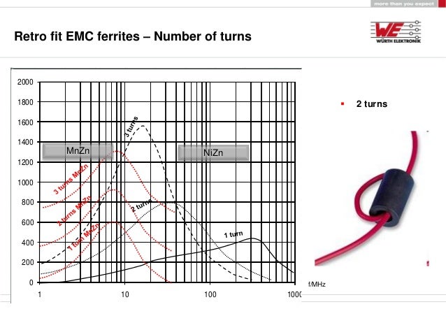
A ferrit bead adds like 4-8µH of inductance. if the cable is passed trough once.Ferrites on cables ONLY do something for common mode RF noise
Of cause!grounded will have a vastly different impedance for RF than for LF.
Ferrites on cables ONLY do something for common mode RF noise. They are mostly there to ensure the equipment passes emission and or immunity tests for RF (the home is filled with this these days).
If my examples satisfy your definition of an ground loop. Than this happened not so loge ago.When was the last time you solved a groundloop with a ferrite ?
This is what i'm trying to say!The influence a cable can have largely depends on the used gear.
No! Its Sufficient to test it under the challenging and extrem conditions, from there easy to judgedSo you feel a cable test should be for all conditions including microphone, TT cartridges, various extremes that might occur using transformers (peaking) or passive pre-amps ?
Don't we all? I think no one is surprised from the test result or changed his/her mind about this cable because of the test.Basically you agree the cable is snake oil
Yes. This Difference in potential can be created by Induction.
Why not use an relative realistic "worst case".
600-1200Ohm would be my suggestion maybe 1K to make the math easy? it dose not relay matter.
I Connected a PCs internal sound card via "3,5mm to RCA cable" to the Amplifier and got noise issue if i move the mouse.
The amplifier was double insulated an if connected to nothing else expect power an PC the noise was mostly gone.
Connecting its case properly to Ground made the noise worse.
Adding 2 ferrite on both sides of the RCA cable with 2 or 3 turns solved this
No! Its Sufficient to test it under the challenging and extrem conditions, from there easy to judged
its performance under ideal and non challenging conditions.
The other way around its impossible.
And this was the only test able to show a real difference.and that's exactly what was tested by Amir. Just not calibrated what could be done (and more) in an EMC lab which Amir does not have.
Do you listen?That is a LOT of combinations.
Whats the return part for the current?o lower HF common mode currents in specific cases. It will do NOTHING for ground loops
It effectively is a common mode choke and thas what they doWhat the ferrite does in your case is increase the impedance for common mode but NOT for the signals traveling through that cable. A lower HF
Well It effectively is a common mode choke with a very small inductance. therefore its effect at mains frequency is negligibly small.(does nothing for mains leakage etc.)
Yes i know that's what common mode chokes doA ferrite is only filtering common mode. It increases the common mode impedance and not the differential mode (what is passing through the coax).
And the ideal Connection would have:You could only change the common mode impedance of that cable and thus won't influence the FR.
I know. I have some education about soft magnetic materials.Only specific ferrites (there are different types for different freq. bands)
If you mean having high losses at audible band then yes only some.only do something just outside of the audible band.
The conclusions that can be drawn from the test have limits and don't apply in all cases.So you do feel that the test was inconclusive because not a lot more tests were done under many extreme conditions

Do you listen?
Just one measurement with a relativity High known resistor is sufficient to calculate the performance from there.
EDIT: one change mayor change to the setup now add 1K
Yes i know that's what common mode chokes do
1. the use of a defined as source impedance 1K
Why? Why not? the higher the better the captive cable influences show up. Same reason one would scale the y axis to +-1dB
Same reason we look at the distortion graph down to -140dB and not just cut it off at -115 and say its perfect. its nice to see
2. Replace the transform test with something like this.
Play a Sine sweep at given volume. still not calibrated or linear but reproducible and comparable.
Also Rejection vs. frequency
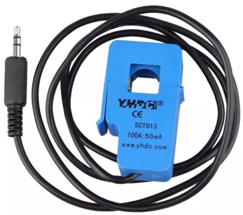
also. Terminate the cable under test in something like this
Connect there grounds together so measured Loop impedance is only(mainly) cable impedance + contact impedance.
3. (Tahts an independent/extra test)
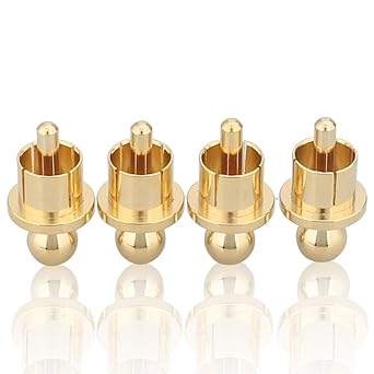
Connect one side to of the cable to the AP analyzer and short the other side with an end cap.
Something like this but the other way around...
Then use a audio amplifier and a resistor to apply Commenmode Current to to the shorted end.
Play a sine sweep and you Have a common mode current picup/rejection over frequency.