
-
WANTED: Happy members who like to discuss audio and other topics related to our interest. Desire to learn and share knowledge of science required. There are many reviews of audio hardware and expert members to help answer your questions. Click here to have your audio equipment measured for free!
You are using an out of date browser. It may not display this or other websites correctly.
You should upgrade or use an alternative browser.
You should upgrade or use an alternative browser.
Townsend Isolda cable
- Thread starter Purité Audio
- Start date
- Status
- Not open for further replies.
Here's a red deer dragging a cable around. This is what this entire "conversation" is like really...Oh dear.

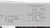
The switch produces a step, 0 to 1V which sends DC to the other end, with the capacitance charging up and the magnetic field building up, drawing a net DC. If the wires were infinitely long, the steady DC Voltage divided by the current would be a resistance equal to the characteristic impedance of the cable. That is the start of lesson 1 in transmission line theory when I went to university. see attached[/QUOTE
It dosnt send dc, dc is constant, it sends a step, which is almost like sending a square wave. Look at the fourier of a step. the reflections only occur on the step then settle out into dc. Do you remember any signal proccesing? The signal times the transform function? The e field and b field only build during the step! Then you reach equilibrium, DC and nothing changes.
From your chapter 14.
" When a voltage is suddenly applied to one end of a transmission line, both a voltage “wave” and a current “wave” propagate along the line at nearly light speed." So a step response. Why talk about infinite lines when ares are a tiny fraction of a wave length? Your clutching straws.
" When a voltage is suddenly applied to one end of a transmission line, both a voltage “wave” and a current “wave” propagate along the line at nearly light speed." So a step response. Why talk about infinite lines when ares are a tiny fraction of a wave length? Your clutching straws.
Speedskater
Major Contributor
What the linked paper in post #279 is that they are using the simplified Radio Frequency Characteristic Impedance formulas that only work well from about 1/2 megahertz and up. The audio frequency formulas are way more complex.
And you can't just close a switch at DC. That doesn't meet the definition of DC (you have to wait till the voltage stops changing).
And you can't just close a switch at DC. That doesn't meet the definition of DC (you have to wait till the voltage stops changing).
It is a voltage readout. It depends upon how many volts you put in at the amplifier end. It could be 1mV, 1V or 100V, the garphs would all be the same. These tests were done with about 1 volt. but that is irrelevant.
Well it does make a difference. So your getting 1 volt across a short for zero db? I doubt it. Im confused. I tought you were measuring the voltage from speaker ground to amp ground, but now you say your measuring around a volt?
solderdude
Grand Contributor
There is no extra R, C, or L, as it might distort the results.
Wasn't clear to me if it was. Have you done the same test with the inductor + boucherot ?
The main reason for the test in the first place was to find a simple measurement that quantified the difference between different geometries. The easiest way is to see what the voltage drop was across a single conductor.
And it clearly does show geometry matters. The geometries are quite unconventional, aside from the round conductors spaced closely apart.
Most cable manufacturers try to lure buyers with exotic materials being used as isolators or conductors. Your 'thing' is geometry and only one type (flat conductors very close basically forming an unusually high capacitance in parallel to the amp.
I understand why you chose the dB scale which shows the differences between the cable geometries.
The real world effect of the increase in cable resistance, however, when looking at the actual signal that counts in real life (the signal across the amp and speaker) are really small. Small enough to not be audible at all.
That's what is ticking off most of the folks here and is what they find dishonest. I kind of agree.
yes, geometry matters and yes your cable is technically 'flatter' in response and obviously has less 'upper treble roll-off' compared to 'normal' cable.
With stats and very low impedance speakers this might even become audible when long lengths are used.
That said. When one is using amps near the speakers (mono blocks) or a stereo system with the power amp between the speakers and only 2 meters per speaker non of this will be audible (yours and 'normal' cable) in any practical sense.
Why pay a premium for a weird looking cable when it is not audible ?
- Joined
- Mar 22, 2019
- Messages
- 129
- Likes
- 30
It is in the industry standard form of relative measurement, expressed in dB http://www.sengpielaudio.com/calculator-db.htm and see table..Well it does make a difference. So your getting 1 volt across a short for zero db? I doubt it. Im confused. I tought you were measuring the voltage from speaker ground to amp ground, but now you say your measuring around a volt?
Assume 1V amplifier output into 8ohms. The current = 0.125A. The resistance of Isolda at 20mm x 0.25mm = 5sqmm. From wire tables this equates to 0.0033 ohms per metre. 14metres gives 0.046ohms. 0.125A through 0.046ohms gives 0.006V. Therefore, 0.006/2 = 0 .003V dropped across the two black terminals, for 1volt in. Is this what you want, or more?
Wasn't clear to me if it was. Have you do
The real world effect of the increase in cable resistance, however, when looking at the actual signal that counts in real life (the signal across the amp and speaker) are really small. Small enough to not be audible at all.
That's what is ticking off most of the folks here and is what they find dishonest. I kind of agree.
Why pay a premium for a weird looking cable when it is not audible ?
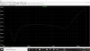
1st graph, voltage from speaker gnd to gnd, what they measured, with a 1volt reference (amp out). so 60 db below signal. Which means, second graph, the signal error at the speaker is less than .05db at 20khz. inaudible, and for the 100th time there are no reflections at audio freqs that matter.
And the usual answer to the last question, believe the fake science so BSaudio makes money.
Attachments
Last edited:
- Joined
- Mar 22, 2019
- Messages
- 129
- Likes
- 30
Yes, the differences are minuscule, but real. You can ignore them if you want low-fi, but not if you want hi-fi.
Speedskater
Major Contributor
Modeling a speaker cable in SPICE is 2 tons of work. You have to make a different model of the cable at each frequency. One old paper made 200 different frequency models. Transmission lines at low frequencies are strange things indeed.
OP
- Thread Starter
- #292
Tee Hee.Yes, the differences are minuscule, but real. You can ignore them if you want low-fi, but not if you want hi-fi.
Keith
I don't care about flat strips. I like to have one of your cables to test. When can I have one?Yes, but we are doing a Zoom session at 6 PM GMT Dec 5, with the cables and yes, you can have the Isolda and flat strips after that to repeat the test.
I look forward to your results.
- Joined
- Jul 25, 2020
- Messages
- 433
- Likes
- 1,069
Hell, I’m a newbie here with limited tech experience, and even I can read through the BS. Just send in the stupid cable already. What are you afraid of?
This is ludicrous.
Edit: Apology...Covid stress response, and I could have been more diplomatic.
Still, the request stands.
This is ludicrous.
Edit: Apology...Covid stress response, and I could have been more diplomatic.
Still, the request stands.
- Joined
- Mar 22, 2019
- Messages
- 129
- Likes
- 30
Some can hear it.Yes, the differences are minuscule, but real. You can ignore them if you want low-fi, but not if you want hi-fi.
see
http://www.townshendaudio.com/PDF/Townshend F1 Fractal speaker cable review HIFI+ 157.pdf
https://www.the-ear.net/review-hardware/townshend-f1-fractal-loudspeaker-cable
There are many more.
It is in the industry standard form of relative measurement, expressed in dB http://www.sengpielaudio.com/calculator-db.htm and see table..
Assume 1V amplifier output into 8ohms. The current = 0.125A. The resistance of Isolda at 20mm x 0.25mm = 5sqmm. From wire tables this equates to 0.0033 ohms per metre. 14metres gives 0.046ohms. 0.125A through 0.046ohms gives 0.006V. Therefore, 0.006/2 = 0 .003V dropped across the two black terminals, for 1volt in. Is this what you want, or more?
Thanks, so like in my sim of an average cable, 60db down. Which corresponds to a .05db freq response variation from 20 to 20k. Inaudible. Still dont get how you used a short to get a baseline voltage. (0db)
You mean some think they can hear it. If those wernt proper blind tests there useless. I have just as many alien abduction stories.
- Joined
- Mar 22, 2019
- Messages
- 129
- Likes
- 30
I thought for a minute that you were a bit open-minded, but If you don't care about flat strips, then your mind is made up and it is a waste of time.I don't care about flat strips. I like to have one of your cables to test. When can I have one?
Speedskater
Major Contributor
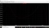
From a very old paper. The characteristic impedance of some speaker cables at audio frequencies.

I thought for a minute that you were a bit open-minded, but If you don't care about flat strips, then your mind is made up and it is a waste of time.
I'd just view it as a lack of bias.
The point of sending a cable is to measure, for which bias is not a factor.
- Status
- Not open for further replies.
Similar threads
- Replies
- 30
- Views
- 2K
- Replies
- 14
- Views
- 846