The last controversy was with the measurements of Klipsch RP-800F. Danny Richie detected a huge hole in his usual measurement at 1 m. Much more softened at 2 m in Audioholics measurements.
It just says that it is a very poorly designed speaker.

The last controversy was with the measurements of Klipsch RP-800F. Danny Richie detected a huge hole in his usual measurement at 1 m. Much more softened at 2 m in Audioholics measurements.
The standard is more like the result shall be scaled to an 1m distance to get comparable SPL readings (needed to judge effienciency of passive speakers). Actual distance depends on what the measurement shall represent and if it is to represent far-field conditions, then the distance actually used (with classic techniques) shall be set to the mentioned 10x the largest dimensions (including depth, btw). And anechoic conditions, of course.About the measurement distance, I thought there was a standard (1 m) but each one measures as he wishes. The logical thing, for me, is 1 meter away and at the listening point
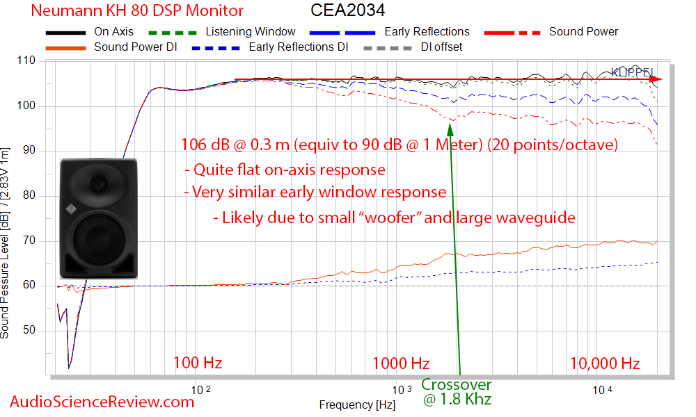
A few weeks ago I reviewed the Neumann KH80 DSP powered monitor. The measurements while very good, did not match manufacturers published graph which showed dead flat on-axis response. Third-party measurements had shown the same so objection was raised that my measurements must be in error. I had to send that sample back to its owner but as it happens, another member had offered his at the same time. Having another sample allows us to both test sample to sample variations and test the hypothesis put forward for difference in measurements.
First, let's review what we had in the review:
And here is the manufacturer "interpolated" response:
View attachment 49056
The small graph compresses differences due to lack of (display) resolution. That aside, we have two differences to investigate:
1. There is no low bass dip a I show.
2. Their response is flatter than what I measured.
Dealing with the second factor first, observation was made that the manufacturer states that the "acoustic center" of the speaker is not the usual tweeter axis but half-way between tweeter and woofer:
View attachment 49057
The hypothesis around bass dip was that I had pushed the speaker too hard in level and therefore it must have limited the low frequency response. This, despite the fact that there was no visible indication from the speaker that it was doing so.
New Measurements
To address both of these factors, I set the levels much lower then before and for the first pass of measurements, I set the reference to half-way between the two drivers which landed it around the edge of the woofer as they show.
Before I show you that, let me show the in-room response:
View attachment 49062
This graph shows the proper measured SPL which is around 85 dB. For some reason when the CEA graphs are calculated for powered monitors, the levels are incorrect. I know what is causing it but don't know why. I will be contacting Klippel on that. For now, accept that the levels were very reasonable and not loud at all. Indeed, the levels were so low that some noise got into the measurements around 20 to 30 Hz which is not material.
Note that the above has a vertical dimension of almost 120 dB so that flattens the response.
For completeness, there is the distortion data as a percentage:
View attachment 49063
Now let's look at the spin data:
View attachment 49064
Clearly this is not the acoustic center as one would define has having the flattest response. The droop in high frequencies clearly indicates we are not on-axis. We can confirm that by looking at the vertical dispersion:
View attachment 49065
The highlighted red graph is showing the "on-axis" as measured. The graphs above it are at -10 and -20 degree so they are more "correct." Translating, following the Neumann recommendation has clearly messed up the measurements.
As to bass dip, we still have that. Note that the new graphs are the more proper 50 dB vertical response which the original review did not follow. So there is more roughness still in there than the review data. This is the CEA-2034 recommendation so what we see, is what is required.
As a sanity check, I select the highest measured frequency of 20 kHz and plot that. Usually this is a clean output with just the tweeter "beaming" (narrowing dispersion). That is NOT what I see in this setup:
View attachment 49068
There are tons of sound sources mixing up to generate this complex soundfield. I can't explain it all. Maybe there are multiple edge differections we are seeing from around the tweeter and woofer rings.
Re-measurements Using Tweeter Axis
Wondering that there may be sample to sample variations, I remeasured the same unit without changing anything but the reference axis to be at the center of the tweeter (as reasonably as I could eyeball it).
Here is our spin data now:
View attachment 49066
This is more reasonable and nearly mirrors the measurement shown in the original review.
Here are the two new measurements side by side:
View attachment 49067
It is pretty clear that if Neumann says the speaker has flat response, its acoustic center can't at the same time be where they say it is. One or the other is wrong. I may have an explanation for this though. See later.
Here is our 20 kHz balloon soundfield again:
View attachment 49069
This is much more correct. We have a single cone now. I am not clear why it is pointing down. Maybe the speaker base is not level? Or drivers are not 100% perpendicular to it? Regardless, the overall picture looks correct so I tend to trust this new measurement with reference axis being the tweeter than below it.
Discussion
Addressing the low frequency measurements, I think most measurements outside of what I am using with Klippel NFS, have some kind of correction for bass region. They do this either because the anechoic room is not anechoic that low, or they are splicing two measurements together. Here is Sound and Recording note on how they measured low frequency response:
Neumann have zero detail so likely have similar restriction. A calibration curve is applied that may be causing it to push up the response a bit versus reality.
Klippel NFS' claim to fame is the ability to be even more accurate than anechoic chambers so if I were to split the tie, I would split it in favor of our measurements being correct. Then again it is possible that my measurement mic has a slight error there. Either way, it is best to not scrutinize these graphs at such close levels.
As to the rest of the response, unfortunately S&R's graph is also of poor resolution:
View attachment 49072
Lots of sins can be buried in low resolution graphs like that.
On the other side of the coin, there is a potential source of variation in Klippel NFS due to reflections from the fixture at higher frequencies.
With respect to acoustic center, I think this is one of those instances where near-field measurement may cause some issues. Specifically, the Klippel system measures the speaker at 1 foot/0.3 meter or so. This heavily accentuates angular differentials. In anechoic chambers attempt is made to measure in the far field by using 2 meter measurement distance or so. This lowers the accuracy of the acoustic center since small differences in location of the microphone there, doesn't make as much angular difference.
Summary
The new data shows that the original measurement data was correct. The bass dip is not level sensitive. And changing the reference point makes the KH80 speaker look a lot worse, not better.
Ultimately I think both anechoic and NFS measurements have their own slight slants. The two measurements may never 100% sync. The "good news" is that there is hardly any anechoic data out there for speakers whereas I hope to build a large database of measurements using NFS system. So as long as we are consistent, our relative scores should hold.
Above all, let's focus on overall picture of these measurements and not 1 or 2 dB here and there.
------------
As always, questions, comments, recommendations, etc. are welcome.
The pink panthers sat this review out because of all the arguing over the last one. One of them may actually need therapy sessions as a result of that ordeal. Please donate a bit of money so I don't have to pay for that out of my own pocket using: https://www.audiosciencereview.com/forum/index.php?threads/how-to-support-audio-science-review.8150/
You making work for me?Thanks for doing this. Could you post the raw data for these remeasurements?
I have always wondered how Klippel manages to convert a loudspeaker measurement in 0.3m into a correct 1.0m measurement.The klippel doesn't go that far. More importantly, it's not supposed to need to.Are both measurements done at 0.3m? Maybe re-measuring at 1m should move back the audio-center between woofer and tweeter (due to tweeter's narrow freq. propagation cone) or at least will eliminate any possible and unwanted driver's vibrations or reflections that might interfere with the final measurements
You making work for me?
I would be interested in calculating the FR deviation from this sample.
")
I have always wondered how Klippel manages to convert a loudspeaker measurement in 0.3m into a correct 1.0m measurement.
As others have said, there is a problem with the measurement angles to the tweeter and woofer when measuring at a distance of 0.3m, compared to measuring at 1m.
In addition, the influence of the baffle depends on the measuring distance (has already been mentioned by others).
Therefore, measurements (in anchoic chambers) for large loudspeakers are carried out at distances of up to 4m (in exceptional cases even further) to keep the problems described above as small as possible.
The Klippel NFS must therefore convert all these influences to a distance of 1m (when measuring at a distance of 0.3m). Otherwise the measurements would be useless.
Even if measurements were not taken on the acoustic axis specified by the developer, the measurement result can later be converted to any point in space as a measuring point - if I have understood the theoretical approach to this correctly.
This can only mean that something is wrong with the second measurement - wasn't the result converted to 1m distance?
In the first measurement, the vertical measurement with -10deg has approximately the acoustic axis required by Neumann - in the diagram in red.
In cyan is the second KH 80 measurement of Amir with now correctly adjusted measuring point in 0.3m distance.
Something went completely wrong!
View attachment 49131
Is there a way to interpret whether a speaker would be good in near field v. farfield? I would like to mount these high on a wall and use for farfield with a WiFi sub. What can the measurements tell us about if this is good idea or not? Would the JBLs be better in this regard?Far field is good. But that is NOT what anechoic measurements typically show. Due to size limitation and modes in the anechoic chamber, measurements are usually NOT in far field but somewhere between it, and near field. In contrast, the Klippel NFS measurements properly show the true far field sound radiation. The larger the speaker, the worse the typical anechoic measurement in this regard.
If you are performing far field measurements outdoor using gating, then you have signal to noise ratio, temperature and humidity variations.
Far field is good. But that is NOT what anechoic measurements typically show. Due to size limitation and modes in the anechoic chamber, measurements are usually NOT in far field but somewhere between it, and near field. In contrast, the Klippel NFS measurements properly show the true far field sound radiation. The larger the speaker, the worse the typical anechoic measurement in this regard.
If you are performing far field measurements outdoor using gating, then you have signal to noise ratio, temperature and humidity variations.
Is this outside the range of being explained by sample variation rather than compression/limiting?It is indeed still there but compared to the previous measurements at 106 dB SPL at 0.3 m or 96 dB SPL at 1 m, this measurement at 79 dB SPL at 2 m or 85 dB SPL at 1 m (according to CEA2034, I presume), has higher levels below 600 Hz: relative to 900 Hz, the peak at around 65 Hz is ca. 1 dB higher while the following dip at around 90 Hz is ca. 0.5 dB higher and the hump between 150 and 600 Hz is ca. 1 dB higher.
Thus, it seems there was between 0.5 and 1 dB of compression in the low to low-mid frequencies in the first measurement due to high SPL.
That pretty much says it all for what you can expect when listening.
As far as I've understood the underlying theory (which I haven't fully digested yet) one can calculate the pressure value (impulse response) at any point in space (from infinity down to right at a point on the speaker cone) once you have data points on a closed surface around the object, with the values being 4-tuples of impulse responses, scalar pressure and vector velocity. Velocity is hard if not impossible to measure acourately, notably at higher frequencies. But one can measure pressure gradients which can help out. This requires an additional surface of measurement at some distance from the first one.I have always wondered how Klippel manages to convert a loudspeaker measurement in 0.3m into a correct 1.0m measurement.
~50” is the middle of the recommended listening distance, if you keep the same vertical height (between tweeter and woofer) but move the mic 50” away, I wonder what that response would look like, it would be at a smaller vertical degree, so likely less droop.Clearly this is not the acoustic center as one would define has having the flattest response.
But it is conflicting the known Neumann design philosophy (at least Markus Wolff keeps emphasizing it) which is: All speakers are designed to be flat on-axis anechoic, which means baffle step fully compensated, diffraction fully compensated. Which means off-axis it cannot and does not measure flat, nor does power response (as measured eg in a reverberation room).That pretty much says it all for what you can expect when listening.
This should not be the case, as this is the most unusual thing in the whole system - even if I don't understand itCould the Kippel system be trading some effectiveness/accuracy for higher practicality?
There has to be a trade-off for not measuring (actually) in free-field conditions.
But the statements all seem to refer to a single-source. Because Klippel continues and says to measure multi-way speakers:The sound field generated by the source is reconstructed by a weighted sum of spherical harmonics and Hankel functions which are solutions of the wave equation. The weighting coefficients in this expansion represent the unique information found in the near-field scan while gaining a significant data reduction.
The near-field data, measured at a high SNR, is the basis for predicting the direct sound at larger distances. This avoids diffraction problems of classical far-field measurements (non-homogeneous media).
That again I can easily understand. Only by measuring the individual drivers individually can their "behaviour" be extrapolated for any distance and by combining the individual driver measurements the frequency response can be determined for any point in the room.The sound pressure output of loudspeaker systems with multiple transducers (line sources, sound bars, 3-way systems, etc.) can be determined by measuring each transducer separately using a multiplexer. After the holographic processing the sound pressure of the individual source can be superimposed to determine the total sound pressure output of the audio device.
At low frequencies the limiter intervenes much more. Here is a comparison of the first and second measurements, normalized to the second measurement:Thus, it seems there was between 0.5 and 1 dB of compression in the low to low-mid frequencies in the first measurement due to high SPL.
Looks like you've nailed the problem.But the statements all seem to refer to a single-source. Because Klippel continues and says to measure multi-way speakers:That again I can easily understand. Only by measuring the individual drivers individually can their "behaviour" be extrapolated for any distance and by combining the individual driver measurements the frequency response can be determined for any point in the room.The sound pressure output of loudspeaker systems with multiple transducers (line sources, sound bars, 3-way systems, etc.) can be determined by measuring each transducer separately using a multiplexer. After the holographic processing the sound pressure of the individual source can be superimposed to determine the total sound pressure output of the audio device.
But if this is the case the measurements of a multi-way loudspeaker in 0.3m are not transferable to 1m distance by the NFS.