• WANTED: Happy members who like to discuss audio and other topics related to our interest. Desire to learn and share knowledge of science required. There are many reviews of audio hardware and expert members to help answer your questions. Click here to have your audio equipment measured for free!

Fun with vinyl measurements

dlaloum

Major Contributor
Joined
Oct 4, 2021
Messages
3,138
Likes
2,401
But the Bang & Olufsen MMC 6000 uses a comparatively long (x? mm) beryllium cantilever (I can’t find many good photos of this and, unfortunately, the diamond tip is missing on this specimen):

View attachment 186496

And a calibration plot for a typical production unit shows exemplary response to 40K:

View attachment 186497

Once again, success comes from the synergy of the complete system rather than the advanced strength of an individual design feature.
Would need to check - but there is no way a solid rod cantilever would achieve that - I would bet that this one is a beryllium tube...

With that type of cantilever Technics achieved the lowest ever tip mass... (although theirs was a tapered boron tube) and assuming a Beryllium tube cantilever here - the cantilever resonance would most likely be up at well over 30Khz - and from that calibration plot - it looks like it is around 40Khz

If your cantilever is intact - this one is definitely worth while sending for a retip - to someone who does "Real" retipping... ie: put a new rock on the end of the old cantilever - don't send it to someone who replaces the old cantilevers - none of the current solid rod cantilevers will match this - regardless of the material used.

The Technics EPC100 & EPC205, as well as the Shure V15VMR and a number of others used full length beryllium / boron cantilevers to achieve these kinds of results.... - but these were all tubes - not rods
 
Last edited:

stereoplay

Active Member
Joined
Oct 2, 2021
Messages
109
Likes
115
Location
Deutschland
Wow&Flutter of a Dual CS628 Direct drive
 

Attachments

  • Dual CS628.png
    Dual CS628.png
    191.2 KB · Views: 99

stereoplay

Active Member
Joined
Oct 2, 2021
Messages
109
Likes
115
Location
Deutschland
I'm really impressed by this old belt driven TT, Garrard GT-20:

Screenshot 2022-04-10 18.20.06.png


Please bear in mind that I use a gyroscope, so no test record can add additional W&F.
1% too fast, but really low W&F. Most of the 0.55Hz component is filtered out in the weighting filter (-10dB):
1649608223451.png
 

JP

Major Contributor
Joined
Jul 4, 2018
Messages
2,292
Likes
2,468
Location
Brookfield, CT
That 0.55Hz component is pretty significant, and appears to be ramping.
 

stereoplay

Active Member
Joined
Oct 2, 2021
Messages
109
Likes
115
Location
Deutschland
Yes, that is true. The 0.55Hz component is fluctuating from time to time. I made some measurements, but the readings are always similar.
 

MattHooper

Master Contributor
Forum Donor
Joined
Jan 27, 2019
Messages
7,288
Likes
12,193
I don't have an easy way to measure mine, but frankly I'm going with the ignorance-is-bliss approach :)
 

JP

Major Contributor
Joined
Jul 4, 2018
Messages
2,292
Likes
2,468
Location
Brookfield, CT
Yes, that is true. The 0.55Hz component is fluctuating from time to time. I made some measurements, but the readings are always similar.

This from a DD motor FG. This is two revolutions that almost perfectly sit atop each other.


DK2412D015_Motor FG_Post Refurb.png
 

Ha-Ha

New Member
Joined
Apr 10, 2022
Messages
3
Likes
5
Hello,

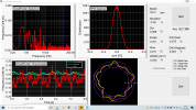
I found this forum and discussion while searching for a detailed technical manual on the Technichs SL1200mk7. I just want to add to the fun with some recent measurements on the speed stability of a SL1200mk7. Speed is measured by counting periods between optical pulses reflected from the strobe dots along the platter rim. Measurements are made using a time-interval counter in continuous (back-to-back) sampling mode with a sampling time corresponding to two periods of the strobe dot pattern. The first figure shows the angular variation of individual frequency samples, with a total of 57 revolutions overlaid. The highly reproducible pattern suggests that the measured variations are due to geometric variations of the strobe dot pattern, and not an actual variation in the platter's rotational speed. I guess this could be investigated using a high quality test record.

1649630101339.png

Since frequency measurements are continuous and synchroneous with the actual rotation of the platter, it is easy to compute a synchroneous low pass filtered rotation speed by computing the moving average over exactly one full rotation. Such averages shown below as a deviation from the nominal rotation speed of 33 1/3 rpm.
1649631199004.png

The average speed deviation is 0.001 % and the variations around this value (averaged over one full rotation) are < 0.0015 % in magnitude. A fuller view of the data are captured in the frequency stability plot shown below.
1649632282021.png

The (modified) Allan deviation indicates the typical relative difference between consecutive values of the average frequency/speed, for a given averaging interval (tau). The first 'dip' of the stability corresponds to an averaging interval of one full rotation and simply reflects what is shown in the first figure, namely that the variations in measured speed are very reproducible from one rotation to the next. For averages over more than 5 rotations (9s), the differences are less than one part per million. The data presented here do not shown any detectable speed drift at a level 10^-7.

All in all, the SL1200mk7 has excellent speed accuracy and stability. The method used to measure the speed of rotation is likely influenced by geometrical imperfections of the strobe dot pattern and is therefore not a reliable indicator of short term speed variations (flutter). The measurements nevertheless suggest an absolute upper bound of 0.2 % of short term speed variations. For measuring short term variations, it would be better to directly access the speed sensing circuitry of the SL1200mk7 and the phase deviation values of the internal quartz lock loop. Any pointers to a service/repair manual?

Added: The strobe dot pattern along the platter rim is designed for a visual indication of speed accuracy. Circular dots makes the measurement setup sensitive to slight eccentricities. It would have been better with square shaped strobe dots. The optics of the measurment setup will likely be tweaked to get reduced sample-to-sample variations.
 
Last edited:

Ha-Ha

New Member
Joined
Apr 10, 2022
Messages
3
Likes
5
I found a service manual for the SL1200mk7. It seems one should be able to measure speed related signals directly from pins 1-3 on the main PCB. Speed is apparently measured using some kind of Hall sensor. The manual does not really give any details on what the different pulse signals are.

1649760048348.png
 
OP
Balle Clorin

Balle Clorin

Major Contributor
Joined
Dec 26, 2017
Messages
1,330
Likes
1,209
Another test record
1650218255422.png


The same test record with perfect Azimuth, thanks to @stereoplay
4B40218C-56E7-414D-9141-26F180980F41.png
 
Last edited:

DSJR

Major Contributor
Joined
Jan 27, 2020
Messages
3,387
Likes
4,522
Location
Suffolk Coastal, UK
Yes, Dynavector uses a very short 1.7mm diamond rod:

View attachment 186495

But the Bang & Olufsen MMC 6000 uses a comparatively long (x? mm) beryllium cantilever (I can’t find many good photos of this and, unfortunately, the diamond tip is missing on this specimen):

View attachment 186496

And a calibration plot for a typical production unit shows exemplary response to 40K:

View attachment 186497

Once again, success comes from the synergy of the complete system rather than the advanced strength of an individual design feature.
I have a good new MMC20CL with fancy tip on a sapphire cantilever and can tell you this about these designs going back to the early 70's SP15 model. They're VERY temperature sensitive and sound dull and dreary if the temp is below 72 degrees or so. There was a selling point with the Beogram 4000 which came with the SP15 and when connected to the mains, the temp under the closed lid was slightly higher deliberately - this via B&O back in the 70's and not made up! In some ways, I prefer the less well measuring and more 'raw' tones of the lower model MMC20-EN

My MMC 20CL is smooth toned, low surface noise but bland for rock music (mine is in the later black coloured half inch adaptor). HiFi Choice measured it at around 70 degrees F and the hf wasn't a straight line, but having a gentle 2dB 'MM' response recess in the upper kHz region and a recovery to +1dB by 20kHz, so maybe a slower pen plot, a different test disc to B&O's or a cooler temperature...


Mind you, the ancient but funky toned Denon DL103 MC antique measures well at the beginning of side, yet loses 3dB at hf by side end due to the conical tip. None of the fans seem to notice this, but then, they haven't done comparisons with a good CD transfer at beginning or end of side, let alone measured it as many tech reviewers have.
 

Ha-Ha

New Member
Joined
Apr 10, 2022
Messages
3
Likes
5
Just for fun, here is the speed deviation for full rotations of the platter of a Technics SL1200MK7. This is based on the same data presented above, but shows the speed deviation for a time series of complete rotations, resolved for every 2nd dot of the platter strobe pattern. A total of 56 rotations are shown. Time-intervals (periods) for full rotations are calculated by taking difference of time-interval-counter timestamps for all pairs of samples spaced 91 samples apart.

1650283347725.png
 
Last edited:
OP
Balle Clorin

Balle Clorin

Major Contributor
Joined
Dec 26, 2017
Messages
1,330
Likes
1,209
Thanks for the instructions. I have just one question which I don't manage to fix and that is to "change calibration file". Should I import it as .txt in the frequency response option? I don't see where you change calibration file unless you do a measurement in the preference menu.
Sorry I did not see this,
REW has a set of tabs to the left after importing a wav file or any measurement , on the tab you can click to “change calibration”
 

Thomas_A

Major Contributor
Forum Donor
Joined
Jun 20, 2019
Messages
3,459
Likes
2,446
Location
Sweden
Sorry I did not see this,
REW has a set of tabs to the left after importing a wav file or any measurement , on the tab you can click to “change calibration”
Thanks, I found that out after some time.
 
Top Bottom