• WANTED: Happy members who like to discuss audio and other topics related to our interest. Desire to learn and share knowledge of science required. There are many reviews of audio hardware and expert members to help answer your questions. Click here to have your audio equipment measured for free!

Audiophonics HPA-S400ET Review (Stereo Amplifier)

Rate this amplifier:

  • 1. Poor (headless panther)

    Votes: 1 0.2%
  • 2. Not terrible (postman panther)

    Votes: 4 0.8%
  • 3. Fine (happy panther)

    Votes: 38 7.9%
  • 4. Great (golfing panther)

    Votes: 440 91.1%

  • Total voters
    483

Davide

Senior Member
Joined
Jul 6, 2020
Messages
466
Likes
175
Location
Milan, Italy
The question of the decade. I have no idea why they don't do it with all the gear. It makes sense to run them out of phase. The one drawback is that the speaker terminals are backwards. Like the 2 negatives/speaker-grounds are not common because they are out of phase. It's not uncommon for car audio amp users/installers to tie the amp grounds together and fry the amp. I've seen it many times. Other than that I don't see any reason to not to run them 180 degrees out of phase. :D
So theoretically, it would be beneficial to apply it to my NC502MP too, right? (as well as all the other amplifiers in the world :D)
Inverting the phase on a channel and then connecting the speaker terminals in reverse is trivial to do ...
But how do I know that the technique is not already adopted by design in the Hypex powered modules?
(sorry for ot)
 

Doodski

Grand Contributor
Forum Donor
Joined
Dec 9, 2019
Messages
21,540
Likes
21,825
Location
Canada
Inverting the phase on a channel and then connecting the speaker terminals in reverse is trivial to do ...
It requires additional circuitry. Usually a OP amp or more and a buffer maybe plus the peripheral circuitry for the OP amp(s) and (+) and (-) voltage rails for the OP amps. It can get complicated pretty fast. OP amps are pretty cool and the basics are not too too difficult to understand although to do them properly requires a solid foundation/education in them and some experience. The math can be daunting for some. Maybe you have all that?

But how do I know that the technique is not already adopted by design in the Hypex powered modules?
Research the amp & schematic or get a oscilloscope and check the circuitry to determine what the topography of the circuitry is.
 

Davide

Senior Member
Joined
Jul 6, 2020
Messages
466
Likes
175
Location
Milan, Italy
It requires additional circuitry. Usually a OP amp or more and a buffer maybe plus the peripheral circuitry for the OP amp(s) and (+) and (-) voltage rails for the OP amps. It can get complicated pretty fast. OP amps are pretty cool and the basics are not too too difficult to understand although to do them properly requires a solid foundation/education in them and some experience. The math can be daunting for some. Maybe you have all that?


Research the amp schematic or get a oscilloscope and check the circuitry to determine what the topography of the circuitry is.
No I just meant that I just have to take the cable coming from the source (a channel) and reverse its hot / cold poles. Then I invert the poles of the cable that comes out of the amplifier and goes to the relative speaker.

However I read that power supply pumping is only a problem for half bridges. Not for full bridges.

"The power supply voltage buses of half-bridge circuits can be “pumped” beyond their nominal values by large inductor currents from the LC filter. The dV/dt of the pumping transient can be limited by adding large decoupling capacitors between VDD and VSS. Full-bridge circuits do not suffer from bus pumping, because inductor current flowing into one of the half-bridges flows out of the other one, creating a local current loop that minimally disturbs the power supplies."

I have to ask Hypex what topology their modules are and how the power supply is connected on the NCXXXMP series.

However, since Audiophonics applies the technique I assume that the 1ET400A modules are half bridge ... so maybe the Hypex too.
 
Last edited:

Doodski

Grand Contributor
Forum Donor
Joined
Dec 9, 2019
Messages
21,540
Likes
21,825
Location
Canada
No I just meant that I just have to take the cable coming from the source (a channel) and reverse its hot / cold poles.
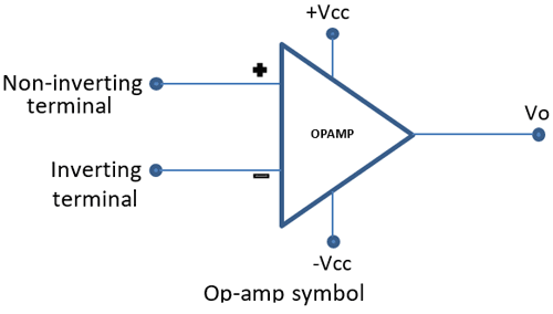
One source signal conductor is a ground reference and the other is the signal conductor. So they can't be reverse connected. The ground is the reference and has to remain as the ground. The (+) signal conductor needs to be reversed 180 degrees in phase. That's why the OP amps are required. To reverse the phase 180 degrees. By using the (-) inverting input of a OP amp the output will be 180 degrees out of phase with the input signal. Then maybe add in a output buffer and it should work. Dependent on the amp circuitry being MOD'ed of course.
A OP amp basic connection diagram.>
Op-Amp-Symbol.png

A very basic OP amp inverting configuration.>
Inverting-Operational-Amplifier.png
 

Davide

Senior Member
Joined
Jul 6, 2020
Messages
466
Likes
175
Location
Milan, Italy
One source signal conductor is a ground reference and the other is the signal conductor. So they can't be reverse connected. The ground is the reference and has to remain as the ground. The (+) signal conductor needs to be reversed 180 degrees in phase. That's why the OP amps are required. To reverse the phase 180 degrees. By using the (-) inverting input of a OP amp the output will be 180 degrees out of phase with the input signal. Then maybe add in a output buffer and it should work. Dependent on the amp circuitry being MOD'ed of course.
A OP amp basic connection diagram.>
I admit I understand little about electronics ...
The idea of reversing the polarity on one channel between source and amplifier and then again between amplifier and speaker is not mine, it is suggested in several web pages and forums.
But maybe I think I understand that since the signal is of the differential type, if I reverse hot/cold it doesn't really change the way the power module is driven. Right?
 

Doodski

Grand Contributor
Forum Donor
Joined
Dec 9, 2019
Messages
21,540
Likes
21,825
Location
Canada
But maybe I think I understand that since the signal is of the differential type, it doesn't really change the way the power module is driven. Right?
The amp circuitry is not balanced. The signal before the amp circuitry changes to single ended as far as I know. So there will be a signal and a ground. Let me get another brain in here to ensure I am correct on this one. Uno momentO.
 

Davide

Senior Member
Joined
Jul 6, 2020
Messages
466
Likes
175
Location
Milan, Italy
@Dlomb11 ,I requested another brain to come and assist. Be a little while
Of course I am happy to wait, thank you!
However I remember Putzeys saying in an interview that the module simply considers the voltage difference between the two input pins ... so I think you are right.
 
Last edited:

Doodski

Grand Contributor
Forum Donor
Joined
Dec 9, 2019
Messages
21,540
Likes
21,825
Location
Canada
Of course I am happy to wait, thank you!
However I remember Putzeys saying in an interview that the module simply considers the voltage difference between the two input pins ... so I think you are right.
With the differential/balanced input you mentioned that changed things. I want to make sure I am not in error. Hence a extra brain.
 

Doodski

Grand Contributor
Forum Donor
Joined
Dec 9, 2019
Messages
21,540
Likes
21,825
Location
Canada
@Blumlein 88 can you assist me with this matter of changing a class D amp phase inversion of channel A versus channel B. It starts here at post #397. I was thinking it was a single ended input and then @Dlomb11 mentioned it is a differential input. So I don't want to make a mistake in advice on how to do the changeover. Perhaps you have ideas on the matter.
 

Davide

Senior Member
Joined
Jul 6, 2020
Messages
466
Likes
175
Location
Milan, Italy
Since we're on the subject I quote Hypex's answer (very fast!):

The NCxxxMP each have synchronous rectification on the main output rails, which will feedback any supply pumping in the supply voltage.
So this means it isn’t necessary to invert the second channel, but you are free to do so if you like.
 

Blumlein 88

Grand Contributor
Forum Donor
Joined
Feb 23, 2016
Messages
20,696
Likes
37,430
@Blumlein 88 can you assist me with this matter of changing a class D amp phase inversion of channel A versus channel B. It starts here at post #397. I was thinking it was a single ended input and then @Dlomb11 mentioned it is a differential input. So I don't want to make a mistake in advice on how to do the changeover. Perhaps you have ideas on the matter.
You might need a better brain than mine.

Firstly I would want to know the circuit of the amp you are doing this to in the first place. There are many possibilities. Secondly the maximum benefit would be likely 3 db if current limited. With some circuit designs it won't matter. I don't see that it would be a problem to flip polarity of the one channel and flip it again at the speaker. The amp doesn't know does it. I doubt you'll observe any benefit from it.

If you want to experiment for free, flip the leads on one speaker. Go into Audacity and invert the phase on that same channel and save the result. Play the new file and you'll get the same effect as any hardware changes.
 

Davide

Senior Member
Joined
Jul 6, 2020
Messages
466
Likes
175
Location
Milan, Italy
I also found this:

Screenshot_20220329-082401_Drive.jpg


Beyond what Hypex says for its modules, if the Purifi modules are full bridge I seem to understand that the technique adopted by Audiophonics is useless.
 

Blumlein 88

Grand Contributor
Forum Donor
Joined
Feb 23, 2016
Messages
20,696
Likes
37,430
The class D amp I have is actually dual mono internally full bridge. Like having a pair of monoblocks in a box. So I've never experienced any such problem. As mentioned if you have a full bridged supply it won't be a problem.
 
Last edited:

restorer-john

Grand Contributor
Joined
Mar 1, 2018
Messages
12,670
Likes
38,767
Location
Gold Coast, Queensland, Australia
NAD have been running amps internally in opposite polarity since the 1980s with the first model, the 2200 (the Powertracker).


1648537087443.png


1648537165222.png


NAD still run amplifiers in opposite polarity, including several of their current Class D offerings.

A side benefit is you can more easily configure the stereo amps for bridged operation (BTL) as it's already essentially most of the way there.

A better solution is to use separate supplies, a better/bigger transformer and/or more filter capacitance in the first place. But for getting a bit more out of the PSU of an amp, it sure does work. There can be issues with amplifiers that have poor channel separation and some strange cancellation effects can be observed in crosstalk testing, but overall it's not a problem.
 

Davide

Senior Member
Joined
Jul 6, 2020
Messages
466
Likes
175
Location
Milan, Italy
The class D amp I have is actually dual mono internally full bridge. Like having a pair of monoblocks in a box. So I've never experienced any such problem. As mentioned if you have a full bridged supply it won't be a problem.
So what topology is 1ET400A?
 

EdW

Senior Member
Joined
Jul 5, 2020
Messages
333
Likes
422
Location
Cambridge, UK
The Purifi modules are half bridge (just check the supply voltages +/-63V and calculate the voltage swings. The 1ET400 develops ~42V rms sine wave - if it was a bridge cct it would give 84V rms).
Wiring the channels antiphase on the power supply balances the load on each power rail which is important at low frequencies if the power rail capacitor banks in the SMPS aren’t to get too large. This is based on the assumption that the low frequency signals in each channel are broadly similar which is what happens most of the time with real music.

In the 1ET400 the polarity may be reversed at the input by swapping the connections in the back of the balanced XLR input connector. - thereby ensuring that the loudspeaker gets the correct polarity signal on both channels I suspect that this is what Audiophonics have done.
 

Davide

Senior Member
Joined
Jul 6, 2020
Messages
466
Likes
175
Location
Milan, Italy
The Purifi modules are half bridge (just check the supply voltages +/-63V and calculate the voltage swings. The 1ET400 develops ~42V rms sine wave - if it was a bridge cct it would give 84V rms).
Wiring the channels antiphase on the power supply balances the load on each power rail which is important at low frequencies if the power rail capacitor banks in the SMPS aren’t to get too large. This is based on the assumption that the low frequency signals in each channel are broadly similar which is what happens most of the time with real music.

In the 1ET400 the polarity may be reversed at the input by swapping the connections in the back of the balanced XLR input connector. - thereby ensuring that the loudspeaker gets the correct polarity signal on both channels I suspect that this is what Audiophonics have done.

Thanks for your answer.
I had not considered reversing the polarity on the power supply of module, but in fact it seems logical and effective.
On the other hand, the inversion of polarity on the input signal does not return. If it is xlr balanced and the poles are reversed, the differential does not change (that's why Doodsky used to say that it needs an opamp). Or I am wrong?
 

EdW

Senior Member
Joined
Jul 5, 2020
Messages
333
Likes
422
Location
Cambridge, UK
Thanks for your answer.
I had not considered reversing the polarity on the power supply of module, but in fact it seems logical and effective.
On the other hand, the inversion of polarity on the input signal does not return. If it is xlr balanced and the poles are reversed, the differential does not change (that's why Doodsky used to say that it needs an opamp). Or I am wrong?
Audiophonics have wired the output of one of the channels in reverse. So the terminal which you expect to be grounded is now the amplifier output but is coloured black. Do not connect this to ground! The red terminal is in fact the ground connection. If the input to the 1ET400 were a single ended RCA then we would not be swapping the polarity of the signals running through the amplifier and we would not have alleviated the load on the power supply at low frequencies. However with a differential input, which is what we have with the XLR input, it is possible to interchange the 2 input wires inside the amplifier such that the positive input becomes the negative input and vice versa. The outputs of the 2 channels are therefore back in phase.
With the Hypex SMPS1200A400 used in the Audiophonics amp it probably isn’t strictly necessary to reverse amplifier polarities since Hypex have designed this power supply to tolerate amplifiers loading the power rails asymmetrically, but the wiring adopted by Audiophonics certainly will do no harm and may marginally improve performance?

EDIT: I noticed that you suggested that the polarity of the power supply of the module is reversed. This may cause some confusion. The power rails are of course unaltered with the +63V from the SMPS1200A400 going to the amplifier positive power connection and the -63V to the negative. The only polarity swaps occur on the input and output terminals - the one cancelling out the other to leave the output in the correct phase.
 
Last edited:

PeteL

Major Contributor
Joined
Jun 1, 2020
Messages
3,303
Likes
3,846
NC252 2 x 250 @ 4 ohms and Purifi one module 425 W @ 4 ohms. I'd hardly call those figures "similar".
Yes at 1% THD (or is it 10%). Nothing wrong with this way of specifying, but personally I prefer Amir's way of specifying the power at the clipping point on the graph itself, instead than at 1% THD. I know he does both nowadays. To me it's more representative especially for Cl;ass D since it's a hard limit. Since Purii has much lower Sinad, you can be well into clipping before you reach 1% THD, but this module is linear until 255W into 4 ohms, that's really the power it can supply. and this implementation of NC252MP https://www.audiosciencereview.com/...d-measurements-of-iom-ncore-pro-pwr-amp.8979/
Clip at 236W into 4 ohms. Similar. They are the numbers I was referring to.
 
Top Bottom