• WANTED: Happy members who like to discuss audio and other topics related to our interest. Desire to learn and share knowledge of science required. There are many reviews of audio hardware and expert members to help answer your questions. Click here to have your audio equipment measured for free!

A/C Isolation Transformers

RayDunzl

Grand Contributor
Central Scrutinizer
Joined
Mar 9, 2016
Messages
13,250
Likes
17,190
Location
Riverview FL
Assuming a reasonably/properly sized isolation transformer at the equipment rack, what is good or bad about them in general?

Do they "store" any energy?

Provide a little impedance advantage or detriment?

HF line noise reduction?

What is the inrush current rushing into when you first power it up?

Why do I have one?
 

March Audio

Master Contributor
Audio Company
Joined
Mar 1, 2016
Messages
6,378
Likes
9,321
Location
Albany Western Australia
OK,

They wont "store" energy per se, however when you switch them off the collapsing magnetic field will provide energy for a very short period.

I would say they will always have higher impedance than the mains direct. It aint as big as your local sub station !

Potential for HF noise reduction, however there is electrostatic (capacative) coupling between primary and secondary dependant on design which can let it through.

The inrush current happens in the period of time while the magnetic field in the primary coil builds up. During this period the inductive reactance is building up so more current flows as at initial switch on there is only resistance.

Measure the DC resistance of the transformer and work out the current flow on 110/240 v :)

Inductive reactance = 2*PI*F*L

Why? Well in your particular circumstances it may help with noise - as always never know for sure without measurement. :)

Equally it may be doing nothing useful :(
 
Last edited:

Speedskater

Major Contributor
Joined
Mar 5, 2016
Messages
1,643
Likes
1,364
Location
Cleveland, Ohio USA
There are two different common types of isolation transformers:
1] Large permanently installed xformers wired as Separately Installed Systems.
Powering the entire audio system.
What's large? Maybe 5000 kVA. A 240V primary is a good thing.
2] Smaller portable plug-in xformers.

The portable xformers lack many of the virtues or the permanent systems.

*************************************
I have a typo here:
Separately Installed Systems.
should be: Separately Derived Systems.
 
Last edited:
OP
RayDunzl

RayDunzl

Grand Contributor
Central Scrutinizer
Joined
Mar 9, 2016
Messages
13,250
Likes
17,190
Location
Riverview FL
There are two different common types of isolation transformers:
1] Large permanently installed xformers wired as Separately Installed Systems.
Powering the entire audio system.
What's large? Maybe 5000 kVA. A 240V primary is a good thing.
2] Smaller portable plug-in xformers.

Mine is smallish - call it 1800VA, and "in the rack". Nevertheless, it "powers" the whole system.

The portable xformers lack many of the virtues or the permanent systems.

What would those be, other than capacity?
 
OP
RayDunzl

RayDunzl

Grand Contributor
Central Scrutinizer
Joined
Mar 9, 2016
Messages
13,250
Likes
17,190
Location
Riverview FL
I would say they will always have higher impedance than the mains direct. It aint as big as your local sub station !

When asking this, my blurry photographic memory thought it had read something about impedance improvement. Here's an example I just found:

http://www.toruspower.com/plain-white-papers/understanding-the-torus-power-isolation-transformer/

"Torus Power units provide astounding dynamic capability to systems by delivering high instantaneous current on demand. Torus Power units present very low impedance to connected electronics. A 20A Torus Power isolation transformer has an output impedance of 0.2 ohms and can deliver 400 amp peak instantaneous current. The Torus Power transformer acts as an energy reservoir when dynamic power is required."

The inrush current happens in the period of time while the magnetic field in the primary coil builds up. During this period the inductive reactance is building up so more current flows as at initial switch on there is only resistance.

I had to think about this one a little, since, I would think that the field collapses and is reestablished with the opposite polarity with the 60Hz input.

What I now think (thank you) is some field is built on the first half-cycle with lots of input current, and it collapses, but the collapse aids the next half-cycle building a bigger field, which collapses and aids the next half-cycle building a still bigger field, until, eventually, at the end of inrush, the applied voltage is being applied to a field that is building itself, and current flow drops to near zero, until some load is applied to the secondary, then the field has lost some energy to the load, and there's some "room" for some input current to replenish it on each half-cycle.

Or something like that.

Why? Well in your particular circumstances it may help with noise - as always never know for sure without measurement.

Measuring with the scope, I don't see any nasties other than the usual mis-shaped pseudo-sine at 60Hz and 170Vpk (or thereabouts). The output of the txfr may have a slightly improved misshapen waveform, though I haven't put both on-screen at the same time. I guess I'll do that next.

Equally it may be doing nothing useful

That's a possibility, though I do think it reduced to the point of elimination mechanical transfomer hum. I haven't had a chance to try it with a guitar amp or other susceptible-to-humming device, except a single instance of an old 3-way electronic crossover that hummed madly plugged into the wall and went silent (except for its old op-amp hiss) when plugged into the iso-txfr.

---

Anyway, I bought it used five years ago, and it seems to be holding its resale value well enough, and it has a nice old-school red voltage display to look at - in and out or off are the choices - with GFCI on the outlets. The output adds a volt or two to the input, so there is a slight step-up or measurement anomaly or something there to think about.

It really ties the rack together - it sits on a pair of bricks, and the premp is on top of that, and fortuitously the top of the preamp is level with the top of the amps, so the bottom layer of the rack is nice and studly.
 
Last edited:

March Audio

Master Contributor
Audio Company
Joined
Mar 1, 2016
Messages
6,378
Likes
9,321
Location
Albany Western Australia
When asking this, my blurry photographic memory thought it had read something about impedance improvement. Here's an example I just found:

http://www.toruspower.com/plain-white-papers/understanding-the-torus-power-isolation-transformer/

"Torus Power units provide astounding dynamic capability to systems by delivering high instantaneous current on demand. Torus Power units present very low impedance to connected electronics. A 20A Torus Power isolation transformer has an output impedance of 0.2 ohms and can deliver 400 amp peak instantaneous current. The Torus Power transformer acts as an energy reservoir when dynamic power is required."


I had to think about this one a little, since, I would think that the field collapses and is reestablished with the opposite polarity with the 60Hz input.

What I now think (thank you) is some field is built on the first half-cycle with lots of input current, and it collapses, but the collapse aids the next half-cycle building a bigger field, which collapses and aids the next half-cycle building a still bigger field, until, eventually, at the end of inrush, the applied voltage is being applied to a field that is building itself, and current flow drops to near zero, until some load is applied to the secondary, then the field has lost some energy to the load, and there's some "room" for some input current to replenish it on each half-cycle.

Or something like that.


Measuring with the scope, I don't see any nasties other than the usual mis-shaped pseudo-sine at 60Hz and 170Vpk (or thereabouts). The output of the txfr may have a slightly improved misshapen waveform, though I haven't put both on-screen at the same time. I guess I'll do that next.


That's a possibility, though I do think it reduced to the point of elimination mechanical transfomer hum. I haven't had a chance to try it with a guitar amp or other susceptible-to-humming device, except a single instance of an old 3-way electronic crossover that hummed madly plugged into the wall and went silent (except for its old op-amp hiss) when plugged into the iso-txfr.

---

Anyway, I bought it used five years ago, and it seems to be holding its resale value well enough, and it has a nice old-school red voltage display to look at - in and out or off are the choices - with GFCI on the outlets. The output adds a volt or two to the input, so there is a slight step-up or measurement anomaly or something there to think about.

It really ties the rack together - it sits on a pair of bricks, and the premp is on top of that, and fortuitously the top of the preamp is level with the top of the amps, so the bottom layer of the rack is nice and studly.


"Energy resevoir"......sounds a bit like marketing speak. Bottom line is you have put a smaller transformer in line with the larger one that supplies your house. I struggle to see it allowing a lower impedance. In any case just how much instantaneous current do you need?

Its actually nearly 30 years since I did my electrical theory, so my description needs refining :) , but I found this ref the inrush current.

Transformers[edit]
When a transformer is first energized, a transient current up to 10 to 15 times larger than the rated transformer current can flow for several cycles. Toroidal transformers, using less copper for the same power handling, can have up to 60 times inrush to running current. Worst case inrush happens when the primary winding is connected at an instant around the zero-crossing of the primary voltage, (which for a pure inductance would be the current maximum in the AC cycle) and if the polarity of the voltage half cycle has the same polarity as the remanence in the iron core has. (The magnetic remanence was left high from a preceding half cycle). Unless the windings and core are sized to normally never exceed 50% of saturation, (and in an efficient transformer they never are, such a construction would be overly heavy and inefficient) then during such a start up the core will be saturated. This can also be expressed as the remnant magnetism in normal operation is nearly as high as the saturation magnetism at the "knee" of the hysteresis loop. Once the core saturates however, the winding inductance appears greatly reduced, and only the resistance of the primary side windings and the impedance of the power line are limiting the current. As saturation occurs for part half cycles only, harmonic rich waveforms can be generated, and can cause problems to other equipment.
 

Speedskater

Major Contributor
Joined
Mar 5, 2016
Messages
1,643
Likes
1,364
Location
Cleveland, Ohio USA
Mine is smallish - call it 1800VA, and "in the rack". Nevertheless, it "powers" the whole system.
With no large power amps, 1800 VA should be OK. Powering all the components from one common outlet or xformer is good. As it provides a very short path for the Safety Ground/Protective Earth wires from one component to another.

What would those be, other than capacity?
When wired as a Separately Derived System it gives much more control over the SG/PE to Neutral connection. This way SG/PE wire doen't have to weave it's way all the way back to the main breaker panel.

*******************************
NOTE:
In my earlier post I wrote:
Separately Installed System
That is incorrect, it's: Separately Derived System
 

Speedskater

Major Contributor
Joined
Mar 5, 2016
Messages
1,643
Likes
1,364
Location
Cleveland, Ohio USA
"Torus Power units provide astounding dynamic capability to systems by delivering high instantaneous current on demand. Torus Power units present very low impedance to connected electronics. A 20A Torus Power isolation transformer has an output impedance of 0.2 ohms and can deliver 400 amp peak instantaneous current. The Torus Power transformer acts as an energy reservoir when dynamic power is required."

To deliver 400 Amps on a 120V circuit, the total source impedance all the way back to the power company's transformer down the street, the total source impedance needs to be 0.3 Ohms or less. However if the isolation xformer input voltage is 240V and the output voltage is 120V, the source impedance can be higher. Twice the voltage and half the current.
 
OP
RayDunzl

RayDunzl

Grand Contributor
Central Scrutinizer
Joined
Mar 9, 2016
Messages
13,250
Likes
17,190
Location
Riverview FL
To deliver 400 Amps on a 120V circuit, the total source impedance all the way back to the power company's transformer down the street, the total source impedance needs to be 0.3 Ohms or less.

There's a Shunyata video where a "dynamic" current measurement on an outlet (nothing special about it since they haven't connected the magical boxes yet) gives 1170 Amperes:

Just a few seconds at 00:28 is what I refer to.

ASCC: Available Short Circuit Current

The rest of it tries to instill FUD, but I thought the raw measurement interesting.

Now I want a new meter!

Example: http://www.extech.com/resources/CT80_UM.pdf
 
Last edited:

Thomas savage

Grand Contributor
The Watchman
Forum Donor
Joined
Feb 24, 2016
Messages
10,260
Likes
16,305
Location
uk, taunton
With no large power amps, 1800 VA should be OK. Powering all the components from one common outlet or xformer is good. As it provides a very short path for the Safety Ground/Protective Earth wires from one component to another.


When wired as a Separately Derived System it gives much more control over the SG/PE to Neutral connection. This way SG/PE wire doen't have to weave it's way all the way back to the main breaker panel.

*******************************
NOTE:
In my earlier post I wrote:
Separately Installed System
That is incorrect, it's: Separately Derived System
Ray does use some fairly large amplifiers.. big Kell monoblocks so possibly plugging them into a 1800va tx is counterproductive?
 

Speedskater

Major Contributor
Joined
Mar 5, 2016
Messages
1,643
Likes
1,364
Location
Cleveland, Ohio USA
Xformers are rated for resistive loads, like old fashioned light bulbs. For audio power amps with linear DC supplies, a 50 % load might be good. Don't know about SMPSs' they work different. Something like a negative resistor. The lower the AC supply voltage, the more current they draw.
 
OP
RayDunzl

RayDunzl

Grand Contributor
Central Scrutinizer
Joined
Mar 9, 2016
Messages
13,250
Likes
17,190
Location
Riverview FL
Ray does use some fairly large amplifiers.. big Kell monoblocks so possibly plugging them into a 1800va tx is counterproductive?

No, they are the little monoblocks (of the series 700/900/1500W @ 4Ω). The power draw is more continuous rather than peaky with the music (Class A with 7 (?) step varying bias.

Using a Kill-A-Watt at the wall outlet and a 'scope on the neutral:

The draw steps up and down with the bias steps on the amps, with a little variation noted with changes in the musical program.

4Vpk drop on the neutral during conduction of 5 Amperes, 8Vpk drop just now, with 13A flowing, at the outlet feeding the rack, with inordinately loud volume.

I agree that the isolation transformer is overloaded if I overload it, but normally, I don't, because that results in unreasonably loud loudness. I wish it were bigger (20 or even 30A size, but it is what it is, and seems to be quite sufficient for my use).

The isolation transformer has minimal case ventilation, the case temperature is 89F right now, the preamp sitting on top of it is 95F.

The jaggedy line is the voltage drop - about 4Vpk (compared to Earth) - on the Neutral, and power is being drawn primarily only during the jaggedy peak coinciding with the peak of the AC input (smooth line, about 170Vpk). The Hot line would also be losing 4Vpk, making its contribution to the flattened top/bottom on the sine.

index.php


I can measure the output of the isolation transformer, but it doesn't show much, other than being stable, with two opposing flattened sines that look almost like the sine above, since both Hot and Neutral have opposing 85Vpk (balanced output).

Parts are coming to take the system off the branched 15A outlet and put in a dedicated 20A outlet with 30A rated cable, so that voltage drop on Neutral will be diminished one of these days.
 

DonH56

Master Contributor
Technical Expert
Forum Donor
Joined
Mar 15, 2016
Messages
7,894
Likes
16,708
Location
Monument, CO
I thought ASCC was meant to test if breakers, GFI's, and all that jazz work. It is to determine the maximum current the circuit will support under shorted conditions, not something expected in normal usage. For a transformer, I think you short the secondary, put the primary on a Variac to control the input voltage, raise the input voltage until you reach the maximum current rating of the primary, and record the secondary current. For an outlet, it is simply how much (short-term) current it will supply before something blows (fuse, breaker, GFI, power cord...) So, it can show how a power cord limits the current, but I do not believe this is any sort of realistic scenario for normal operation, unless normal operation constantly shorts the line... After the initial inrush current, required peak currents are limited by other things, including the output of the amplifier, and of course this still has little bearing on what the amplifier's circuits see after rectification and filtering in the power supply. I put this in the same league as showing an interconnect is better because it has less roll-off at 1 MHz or 1GHz or whatever, not really a reasonable test for an audio design. I can put a cable on a VNA and show it has better bandwidth, lower dispersion, etc. at 10 GHz but does that really matter at 20 kHz? I can put a big honkin' power cord into a tester and do a ASCC test that proves it is better at delivering over 500 A into a short circuit, but if the amplifier only ever requires a tiny fraction of that current, does it matter?
 
OP
RayDunzl

RayDunzl

Grand Contributor
Central Scrutinizer
Joined
Mar 9, 2016
Messages
13,250
Likes
17,190
Location
Riverview FL
I thought ASCC was meant to test if breakers, GFI's, and all that jazz work.

The meter's manual says it is a calculated guesstimation (I would think it doesn't really create a dead short), but it will trip a GFCI since it tests hot to earth.

"Test 4: ASCC Measurements The CT80 calculates the ASCC (Available Short Circuit Current) that a branch circuit can deliver through a breaker in a dead short circuit condition. The ASCC is calculated by dividing the line voltage by the circuit’s line impedance. See equation below:

ASCC = Line Voltage / Hot impedance + Neutral impedance

Use the ► button to simulate a situation where all three conductors (hot, neutral, and ground) are shorted together. Note that this second test will trip a GFCI."

---

Oh Don, you're so practical... Me too, mostly...
 

amirm

Founder/Admin
Staff Member
CFO (Chief Fun Officer)
Joined
Feb 13, 2016
Messages
44,657
Likes
240,885
Location
Seattle Area
There's a Shunyata video where a "dynamic" current measurement on an outlet (nothing special about it since they haven't connected the magical boxes yet) gives 1170 Amperes:

Just a few seconds at 00:28 is what I refer to.

ASCC: Available Short Circuit Current

The rest of it tries to instill FUD, but I thought the raw measurement interesting.

Now I want a new meter!
I have that Ideal 61-164 meter! :D It is almost $350 though so not cheap.

Anyway, I ran some tests.

First is an outlet 1-2 foot away from my mains breaker panel:

Garage 20170313_133606.jpg


We see similar readings as in the Shunyata video at 1,500 amps short circuit (hot+neutral).

Now let's look at what happens when I measure the same in my loft which probably takes 80 to 100 feet of wiring from the panel:

Unloaded Power Cord Loft 20170313_124416.jpg


We are now down to "just" 273 amps. In other words the other 1,300 amps is lost already in the building wiring. Needless to say the effect of any cable now is much, much lower. I did not take a picture of it but where my amp plugs in, using the short cable in the above picture (14 gauge) gave a result of 235 amps. Using the 5-6 foot cable that came with my amp (again 14 gauge) it dropped to 215 amps. So not a big differential although I am suspicious that it made that much difference.

A related question is how accurate the readings are. As noted, the computation is based on impedance measurements of a live circuit relative to line voltage:

upload_2017-3-13_13-56-2.png


The impedance is measured relative to ground because this is a safety check of whether the breaker will trip or not. This is not an accurate method for what we want which is the current carrying capability of neutral relative to hot. The ground per NEC cannot carry current.

To show the unknown factors here, I did another measurement of the loft, this time with the equipment disconnected:

Loaded outlet loft20170313_123516.jpg


The little display on top shows "4 amps" of estimated current in use. But now the current capability has jumped way up to 342 from 270 amps! Likely there is noise or some other factor corrupting the instrument measurements.

As an aside, the little display is ELL or estimated line load. It shows the current usage without having to use a current transformer. It has a nice feature of having a max hold so you can see spikes up. Playing some classical music at reference levels (i.e. a bit above my comfort level) the highest it ever got was 7 amps. This is powering everything from dual mono amps to pre-amp, dac and my PC server. Average was about 5 to 6 amps.
 
  • Like
Reactions: trl

amirm

Founder/Admin
Staff Member
CFO (Chief Fun Officer)
Joined
Feb 13, 2016
Messages
44,657
Likes
240,885
Location
Seattle Area
Adding on, I have a subpanel for my theater that is farther away from the panel. There I read about 270 amps just the same. The subpanel is beefy so probably has 8 gauge wire and such. I then tested outlets that were not on that subpanel in the same area and the reading was about 170 amps. So even beefy wire doesn't help you a ton or get you anywhere close to 1.5 Kiloamps. The video measurements are likely with a short connection to the panel, helped by solid ground connection.
 

Fitzcaraldo215

Major Contributor
Joined
Mar 4, 2016
Messages
1,440
Likes
634
This is all getting somewhat esoteric for me. I have totally lost sight of any conceivable advantage to isolation transformers. Are there any advantages at all for the rest of us? If so, why was the unscrupulous Tice not a success, aside from the repackaged Radio Shack clock he tried to sell as a miracle, of course? But, he did also make many huge power isolation transformers that should have convinced people.

I never tried an isolation transformer. My limited experience with various power "conditioners" is that they are useless snake oil, including, I might add, expensive power "regenerators" such as PS Audio. Aha, but I might only be lucky because power in my area is OK. Thanks to the elegance of introducing FUD into the consumer's mind, many product concepts have been hugely successful. Nowhere more than in audio. Nowhere more than in power for audio systems.

Is there anything at all worth considering in this product category?
 

cjf

Active Member
Joined
Apr 20, 2016
Messages
160
Likes
58
Location
CO
Im struggling to understand how having a large Transformer within inches of the amplifiers that are fed by it could possibly have more resistance and losses then having the same amplifiers being fed straight from the wall, assuming the transformer is of adequate size to perform task.

If you have a hypothetical bucket full of electricity sitting inches away from the amp power supply how can that be more detrimental to power delivery then having the amp wait for adequate juice to arrive from the breaker panel, thru the house wiring, thru the receptacle to the power cable of the amplifier?

What am I missing?
 

amirm

Founder/Admin
Staff Member
CFO (Chief Fun Officer)
Joined
Feb 13, 2016
Messages
44,657
Likes
240,885
Location
Seattle Area
Im struggling to understand how having a large Transformer within inches of the amplifiers that are fed by it could possibly have more resistance and losses then having the same amplifiers being fed straight from the wall, assuming the transformer is of adequate size to perform task.
That's because the transformer itself consumes power.

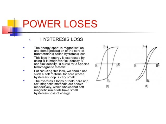
There are two power losses: Load based and non-load base. Load base losses are due to winding resistance. Total power loss is I^R with I being the current consumed and R being the resistance of the winding. Since current is squared, even small resistance results in noticeable losses.

Non-load losses are due to hysteresis and eddy currents. The former is the inability of the core to change on a dime when direction of magnetization changes at the extremes (which occurs continuously in AC circuits). Here is a nice graph showing the losses with some text (the white space between the two curves are the losses):

transformer-8-638.jpg


Finally eddy currents are created within the core and cause it to heat up. Think of secondary currents as tide comes in the ocean around a bend.

There are other losses which are not significant but are there. Magnetostriction for example is when a transformer buzzes due to expansion and contractions of the core. It take energy to do that and that becomes a loss too.

Bottom line, transformers are not ideal devices. They are wonderful in the way they transform from one voltage to another, but as with everything else in life, there is a cost to them.
 
Top Bottom